Removing Fuel Injectors for servicing
Driving along not 1/2 mile from home and our 80 starting misfiring continuously, checked the ultragauge and it showed a P0306 which is #6 cylinder misfire. Drove another mile or so and it continued, so turned around and headed home. Left it a day or so, fired it up again and still misfiring. P0306. Given I'd driven a couple of miles with the misfire and the coolant level was perfect, oil looked clean, no crud under the oil cap and no sweet smell at the exhaust it seemed likely I wasn't dealing with a head gasket issue (yet).
So, I figured it was a good time to do a bunch of maintenance (P0402 was coming on and staying on the last couple of months) and I had an oil leak from the valve/rocker cover. With the help of my older son we got to work.
The plan of attack was to first remove the upper intake manifold since the VSV for EGR is under it and that would allow good access to check the wiring harness near the EGR (one cause of misfires is burnt/shorted wires in that area) and I'd also have good access to the injectors and at that point removing the valve/rocker cover would be easy.
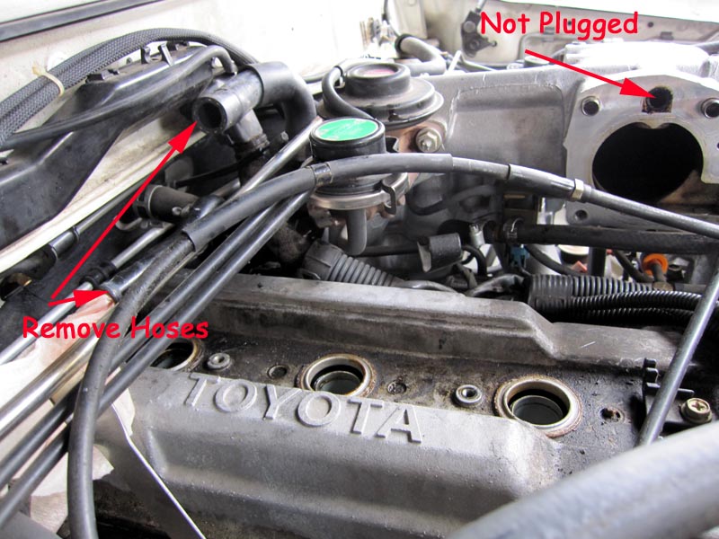
First step was to remove the intake runner going to the upper intake manifold from the s/c and then pull all the spark plugs and leads to inspect and test. Also time for a visual check if the EGR port was plugged - it wasn't. Drained a 1/2 gallon or so from the radiator petcock and then removed the heater lines and heater valve for better access to remove the valve cover and inspect the wiring harness.
The spark plugs all looked good and #6 looked the exact same as #1 - #5 confirming that the misfire was not likely a head gasket failure. The spark plug leads also tested correct with #6 (the longest) at 20k ohms which is less than the 25k ohms the FSM quotes as being the maximum before having to replace leads. I also popped off the distributor cap and the rotor and contacts all looked good, no cracks or arcing etc.
So, next step was to remove the upper manifold which required removing a few bolts (like the power steering bracket and oil dipstick bracket) and then the manifold bolts some of which can easily be reached from above and three (rear bolt and rear 2 nuts on studs) that need to be accessed from below with some long extensions. The three from below can be removed with the starter in place.
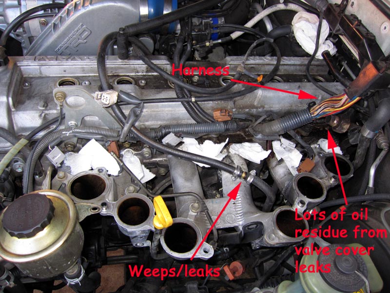
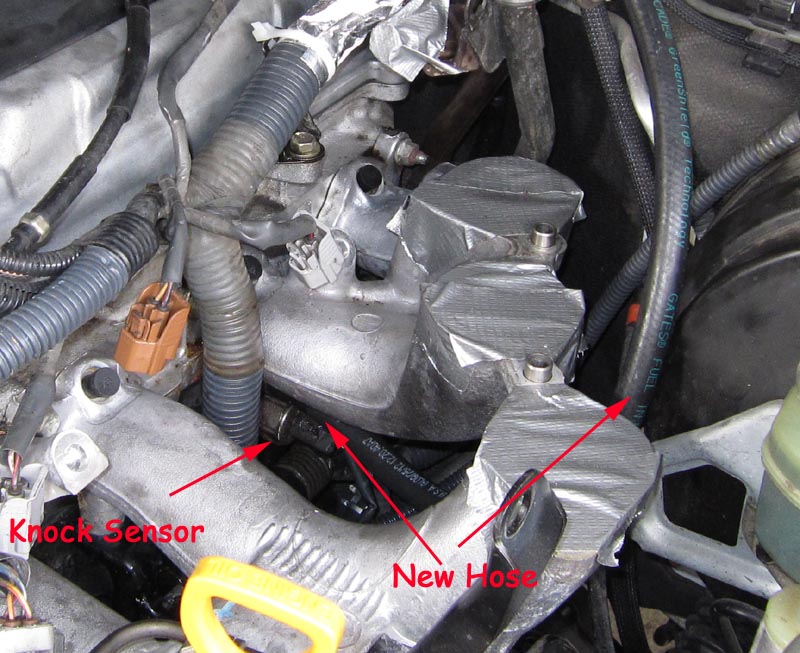
The following picture shows the factory heatwrap removed from the harness area that is very close (too stupid close!) to the the EGR valve (32mm nut, you can use a 1 1/4" spanner to remove). In this case the wiring looked perfect and no signs of melted plastic or even hardened plastic insulation. All perfect. This will later be wrapped with some good quality reflective/lined heat wrap. The oily mess due to the leaking valve cover can also be seen along the head. With the upper intake manifold removed, it was just a matter of removing the inlet fuel line (hard line) from the filter going to the fuel rail. Two banjos are used (one at the filter and one at the fuel rail) so those need to be removed. The fuel filter banjo can be accessed via the top, there's enough room in the gap in the lower intake manifold. We temporarily plugged the injector holes/pockets with some paper towel to keep crud out.
The picture also shows where I've had ongoing leaks/weeps from the barbed joiner from the #1 water bypass hose to the extension hose going to the relocated throttle body (s/c kit). One goal here was to replace this 2 part hose/barb with a single hose.
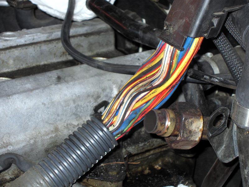
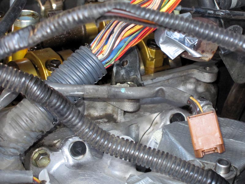
Close up of the wiring harness, all looks perfect. The little black bits are left over adhesive from the OEM wrap. The insulation on each wire was in excellent condition with no signs of heat damage. So, this area wasn't the cause of the P0306. New heat wrap will later cover this exposed area.
I also checked behind the glove box where the main harness goes through the firewall and to the ECU. This is another area folk have reported that on some 80's the harness can rub on sharp metal edges and short. Not the case on our 80, harness perfect and no sign of any area that it would rub through on.
Of course at this point I still haven't found the cause of the P0306 and am running out of obvious possiblities.
With the fuel rail removed and the injectors numbered in plastic bags, I checked the #6 injector and it read 20 - 30k ohms (resistance not constant). Checked #1 - #5 and all read around 13 ohms which matches the FSM spec. So, #6 was dead and that's the cause of the P0306 (#6 cylinder misfire) - success! The five good injectors were then sent to RC Engineering in Southern California for cleaning and testing and a new injector was ordered from Toyota along with gaskets, seals, vacuum lines etc. That was it for the day and since I wouldn't work on the vehicle full time until the next w/end everything was shipped UPS ground to save a few pennies.
The next day some prep work could be started and also checking for the cause of the P0402.
Here's the top manifold (bottom view) showing the VSV for EGR which is also a common culprit for P0402. On testing the VSV the coil showed open circuit where a brand new unit that I've had on hand for the past few years showed 30ohms which is within the FSM spec. So, this is definitely the P0402 culprit and was replaced with the new unit. All new vacuum lines were also ordered to replace these 15 year old originals. Most of the vacuum lines are numbered #0 or #1 and they are the same diameter. Toyota sells a plastic bag that contains about a 2' length of the #0/#1 hose. I ordered 5 such bags, which allowed replacing of all the #0 and #1 lines under/around the intake and also the 2 long lines from the relocated throttle body to the P & R inlets on the EGR modulator.
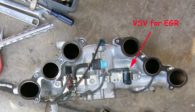
Prior to replacing the lines and parts, everything was removed from the manifold and it was cleaned/scrubbed of all oil/carbon residue. The picture above is prior to cleaning the intake runners. Now it was time to wait for parts to arrive.
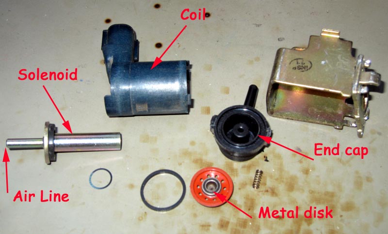
Since the VSV was dead, I opened it up to see what it looked like inside. It's basically an electrically operated solenoid that normally allows air to pass through the End Cap and the Air Line. When the coil activates, the solenoid section becomes magnetised and pulls the metal disk against the solenoid end. There's a tiny o-ring/seal on the metal disk that then prevents air passing through the solenoid/air line section. The orange part of the metal disk assembly is a flexible rubber like material and the small holes are to allow air to pass while providing a flexible structure that allows the metal disk to move to open/seal the end of the Solenoid tube. A few other o-rings/gaskets and a small spring completes the assembly. Anyhow, the coil was open circuit, so into the rubbish with the lot!
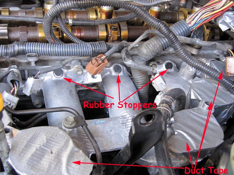
While waiting for parts to arrive and the w/end, it seemed a good idea to do some cleaning and removing of the oil leak and crud. So, I sourced 6 small #000 rubber stoppers from a local Science/Chemistry supply store to plug each of the six injector holes. I also used duct tape to seal the six lower intake manifold runners so I could then gently spray degreaser, scrub and hose off BEFORE removing the valve/rocker cover :)
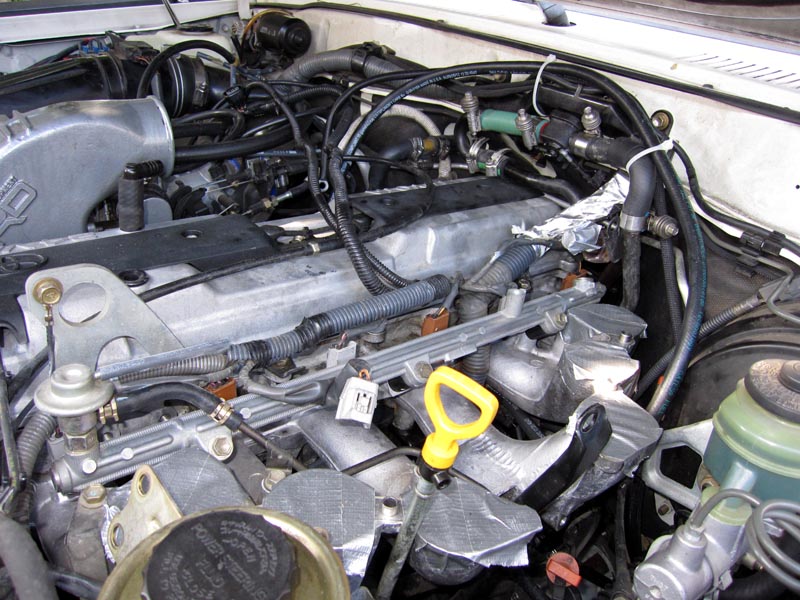
So nice and clean near the injectors and along the top of the head once degreased. Compare to the 2nd picture in this thread of the same area.
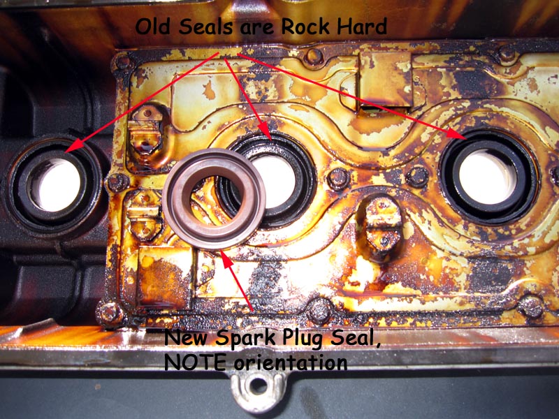
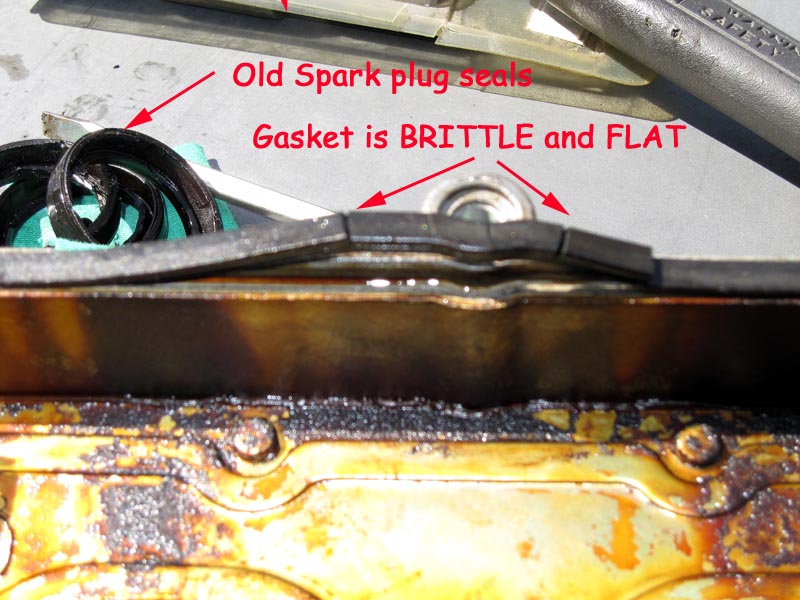
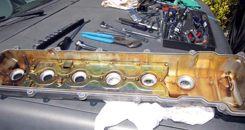
Parts from Toyota (c/o CDAN) arrived along with the w/end so time to get stuck into it. The first job was to remove the old spark plug seals, the PCV grommet and the cover's gasket. The spark plug seals were rock hard and some pushed out with an appropriate socket and hammer taps from above and some just broke into the pieces. The outside edge of the seals are actually rubber coated steel inserts, so be careful to not deform them when extracting them (if they break), otherwise they'll be even harder to remove.
Note how 'flat' the gasket along the cover's edge looks. It was also rock hard and not surprising it wasn't sealing. In fact the rear two bolts were LOOSE when I went to remove them - since the gasket had squeezed down so much over the years as it 'cooked'. Removing the gasket showed how brittle it was as it cracked into pieces. Definitely time to replace it!
With all the rubber bits removed it was time for a good clean with engine degreaser and some vigorous scrubbing. Looks a lot better after cleaning and now ready to install the new spark plug seals. A smear of dielectric grease makes them easier to slide in and a large socket to help seat them all the way in. Just hand pressure is enough, no need to hit them in.
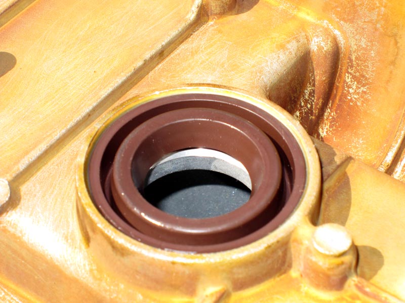
So, this is one seal pressed in
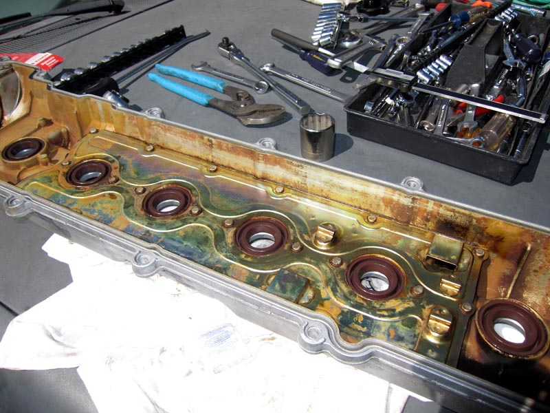
And all completed. A smear of dielectric grease on the inside of each hole so that it will slip easily over each spark plug tube.
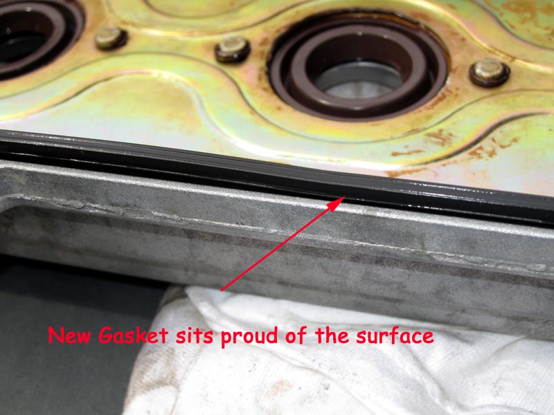
The new gasket with dielectric grease smeared along the length to help it stay inside the channel when the cover is being reinstalled on the head. Notice the new gasket is not FLAT and is also nice and flexible/pliable. This will definitely solve the leaking oil. The original gasket was 15 years old, so it would appear a good idea to replace it every 10 years or so along with the spark plug seals and PCV grommet.
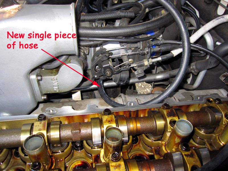
With the valve/rocker cover off it also was a good opportunity (better access) to remove the old throttle body coolant line and replace it with a single longer piece of 5/16" ID hose. You can see the new line installed, the rest will be routed along the firewall and down to the head after the valve cover has been reinstalled and the harness has been re-wrapped with heat reflecting wrap.
With the valve cover all cleaned and new gasket and seals installed it was an easy matter to re-install and then do several passes evenly tightening all the bolts snug. Installed the spark plug leads and put the plastic covers back in place.
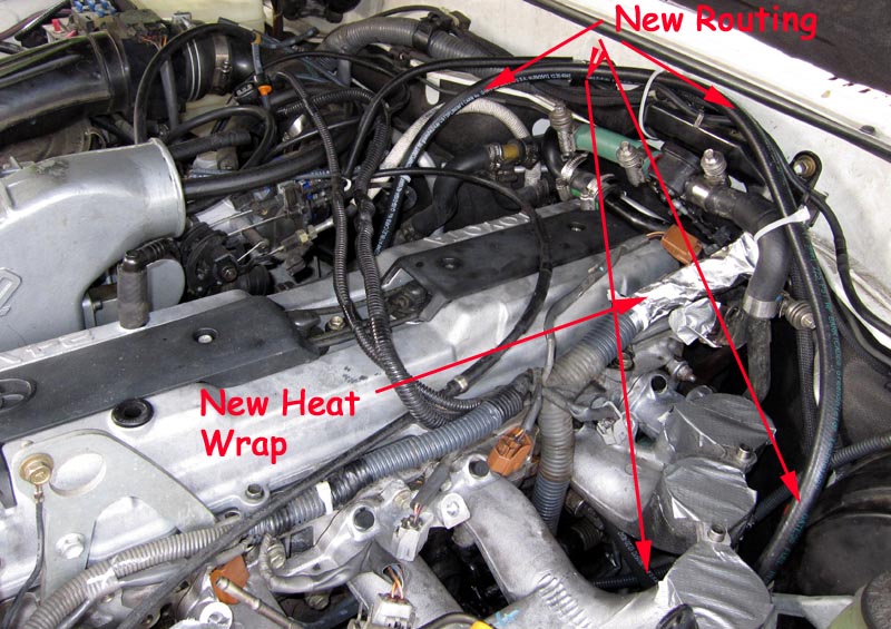
With the upper intake still off it was the time to remove the throttle body hose from the block and connect up the new single section of Gates 5/16" hose. The following picture shows the routing of the new hose along the firewall rather than over the engine. It is a single piece and has a nice straight run to the nipple on the block from near the brake booster.
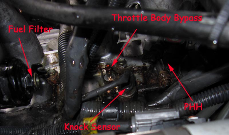
This shows a close up of the bypass nipple on the block before sliding the new hose in place. It was a pain to remove the old hose since Toyota in their wisdom had installed the spring clamp so that it was VERY hard to get a pair of pliers in place to release the clamp tension to slide it off the old hose. The PHH had already been updated to Breeze constant tension clamps and a section of silicone hose. What looks like rust on the clamp and in the general area is just residue/gunk from the valve cover oil leaks and some coolant that seeped from the previous throttle body hose joiner. Having replaced this with a single hose from the throttle body is a nice feeling. The wet coolant is due to some coming out of the nipple when I removed the old hose, I hadn't drained the radiator down far enough, but only about 1/2 litre came out of the nipple since it is quite high up on the block.
The fuel filter does NOT have the banjo/hardline in place since that will be reinstalled when the fuel rail and injectors are put back in place.
Top view showing the new hose routing and the location on the engine block of the nipple. This job was easier than the PHH, but still a pain to get to, mostly due to the limited room and access. To do this job I removed the driver's side tyre and the two skirts in the wheel well and loosened off the bolt holding the brake hardlines (same as for removing the starter motor), but left everything else in place. Removing the OEM hose clamp was the hardest part of the job due to the lack of room and Toyota having installed the clamp in such a way to make it difficult to get a pair of pliers (long nose) in there to release the tension on the clamp to slide it off.
Of course having the upper intake manifold off helps since you can pull the old hose out from above and slide the new hose on from above as well. The OEM tension clamp is slid back over the hose once in place from below the fender and above the starter motor.
The serviced injectors were received from RC Engineering in Southern California. All new o-rings/seals were installed by RC Eng, though I did replace them with new Toyota OEM parts just to be safe. I kept the RC Eng ones as 'spares'. RC Eng also replaced the small filter mesh at the inlet of each of the 5 injectors they serviced. They reported 2 dripping injectors and 3 that had a good pattern, after cleaning all were excellent and much better balanced. With the 6th new injector from Toyota I had everything on hand to re-install everything. With the help of my 15yr old it took about 4 hours to get everything back in place.
First step was to get the injectors and fuel rail back on.
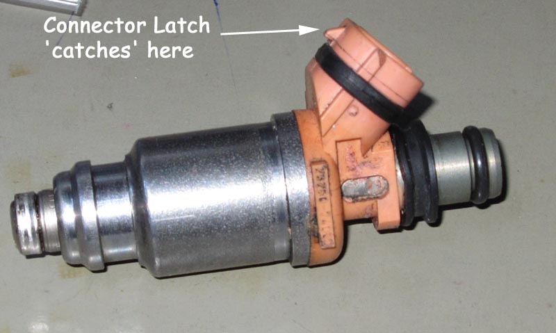
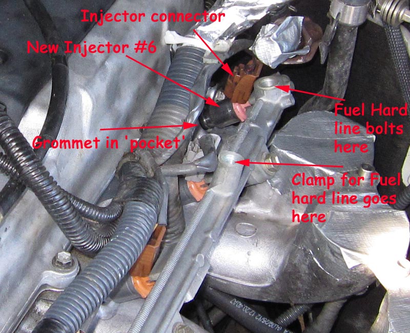
After that the fuel line and banjo connections were re-connected to the fuel filter and the fuel rail. To reinstall the injectors/fuel rail, it's easier to put the bottom grommets/seals into the 'pockets' in the lower intake manifold. Then click each injector back into its connector (so they don't drop), then push each one into the fuel rail (their top o-ring will keep each in place). Here's a picture of an OEM injector (happens to be my dead #6). Top o-ring on the right and the fuel sprays out the left side (no grommet in place).
Once you have all the injectors sitting in the fuel rail its a matter of lining up each injector so it slides into the grommet sitting in the lower intake manifold pocket. It helps to have 2 people to line up the 6 injectors and have them slide home. Then you can pivot the fuel rail a little and slide in the spacer and long bolt (all three). Finger tighten the 3 bolts and rotate each injector a little to make sure they are seating properly and the grommet or o-ring aren't been pinched/deformed. Basically each injector 'floats' between the grommet below and the o-ring and top seal above..
This picture shows the spacer and bolt. This is the fuel rail in its re-assembled position but without the hardline that carries the fuel from the filter yet in place.
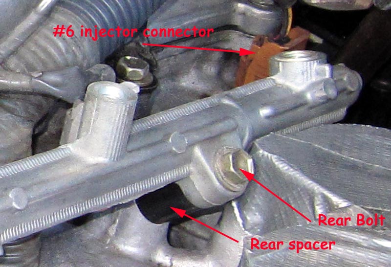
Another view of the installed fuel rail.
Reinstalling everything went along easily and quickly since all bolts from each 'sub-section' that were removed were put into labeled ziplock bags. I've learnt to do this, especially when a repair may take several weeks. Having all the nuts/bolts in labeled bags saves having to rely on memory when presented with a bag containing all the nuts/bolts.
I also take photos during the disassembly steps so I can always refer to a picture if I have any doubts where a particular fastener goes.
With everything reinstalled it took several cranking attempts to re-pressurise the fuel filter and the fuel rail. In total it likely took a good 30 seconds to get the engine started. Once started I cleared all codes with my OBDII ultragauge and then allowed the engine to run a couple of minutes to ensure there were no leaks (fuel or coolant). On shutdown there was a few drips coming from one of the hose ends near the heater valve. A few more turns to tighten up the clamp and then I topped up the coolant in the radiator and then restarted the engine and allowed it to run for 5 minutes or so. Shutdown and no leaks. The next day I drove the 80 several times on trips of around 4 miles in length and checked each time on stopping for any leaks and all was good.
The engine certainly runs very smoothly with the cleaned injectors (+ 1 new one). The misfire of course is gone and we have a running 80 series again and a bunch of maintenance jobs completed.
Here is the original writeup from quite a few years ago that outlines some of the steps to remove just the injectors.
In an attempt to resolve Juan's 80's pinging problem he decided to get his injectors serviced. To do that requires removal of the injectors from the fuel rail and to do that requires removing the plenum from the intake manifold.
http://www.rceng.com/ is the URL for the company that is performing the servicing of the injectors.
It took about 3 hours to get the injectors out - including a trip to the local hardware store to pick up a large spanner.
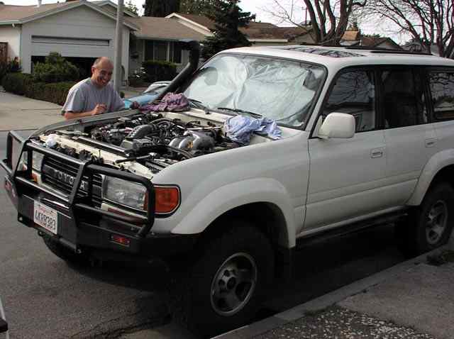
The trick to this job - is remove the bonnet first. You'll be amazed how much more room you have to work with. You have to remove the bonnet to be able to swing the large spanner to loosen the 32mm nut that holds the EGR valve to the hardline.
You have to remove the EGR valve to get the plenum off.
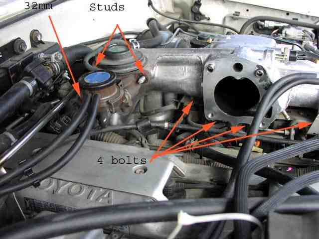
With a Supercharged 80 life is a bit easier since the throttle body is already out of the way and all that is required is to remove the intake runner from the S/C. The picture shows the studs (you have to remove the nuts) that supports the EGR on the plenum. The other arrow points to the rear of the EGR where the 32mm nut is. We found that to remove the EGR valve it was necessary to remove one stud - the one that is visible in the picture. It may be possible to get the EGR off with removing the stud - but it seemed impossible at the time ;-). There are 4 bolts below the plenum that you can barely get to, but easily get to once the plenum has been partially lifted off the intake manifold. The 4 bolts attach two brackets to the plenum. A plethora of hoses & valves and bits are mounted on those brackets. The bolts must be removed so that the plenum can be removed - the brackets & bits remain. Note, we couldn't find a 32mm spanner, so we bought a 1 1/4" instead - worked perfectly fine. Prior to removing the fuel rail, loosen the fuel cap (and leave it loose until you have finished the entire job) and depressurize the fuel rail. To depressurize remove the fuel pump relay and then start the engine and let it run until it stalls (due to lack of fuel). The fuel pump relay is in the front fender on the DS, just below/behind the ABS modulator.
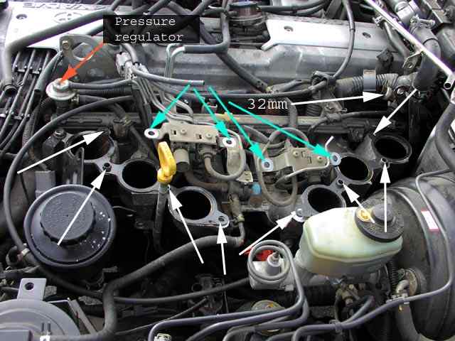
This picture shows what things look like when the plenum has been removed. The white arrows point to the 8 bolt holes. You have to remove all 8 bolts to pull the plenum off - and it has to be lifted vertically off since there are some guides on the intake manifold. Make sure you have two new metal gaskets that go on between the intake manifold & the plenum. Most of the 8 bolts can be removed from above the engine - with double jointed elbows ;-) But a couple of the rear most bolts must be removed from below - make sure you have a lot of extensions! The blue arrows point to the 4 bolt holes that attach the brackets (mentioned above) to the bottom of the plenum. The '32mm' arrow points to the big nut that needs to be loosened to release the EGR valve. The pressure regulator is pointed to (just for the hell of it).
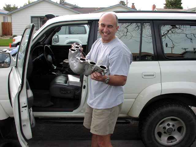
Juan looks happy to finally have the plenum out of the engine bay. Removing the fuel rail and the injectors is now a relatively simple task.
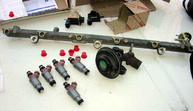
The injectors were returned from service along with a printout of before & after measurements. The picture shows the injectors with new o-rings and gaskets already to install back onto the engine. The EGR valve shown next to the injectors. A new pressure regulator has already been mounted on the fuel rail (far right of the picture).
Installation was reasonably straight forward. The trickiest part is to get all the injectors (with new o-rings & gaskets etc) to line up with the fuel rail and the holes on the head. It's easier to plug the injectors back into the harness so they wont fall to the ground if they slip out of the fuel rail while you're trying to position it. Once installed - start to tighten the three retaining bolts. Don't tighten too much - check that each injector is seating properly by carefully trying to rotate it a bit left & right. If they are seated well, torque down the 3 bolts as per the manual.
We also changed the fuel filter, the pressure regulator, the EGR and the VSV. The vehicle runs smoother but there's still a hint of pinging. I guess Juan will just have to live with that.
![]()