Changing the old MQ from 24V to 12V
My MQ (1980) was shipped with 24V electrics and though I did appreciate the 24V powered winch, the rest of the 24V issues were not things I loved.
Some of the negative issues of the 24V system:
So, enter a donor vehicle (running at the time) that was scrapped for spare parts. A mate pulled the drivetrain for me and I pulled the rest of the stuff over a long day.
Some of the 'bits' from the donor vehicle:
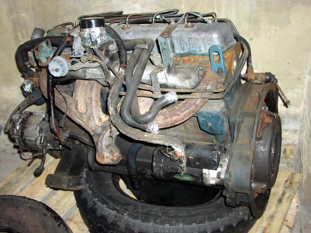
Operating engine (when pulled). The alternator, starter, glow plugs and injection pump control motor are parts that were pulled off to install on my MQ.
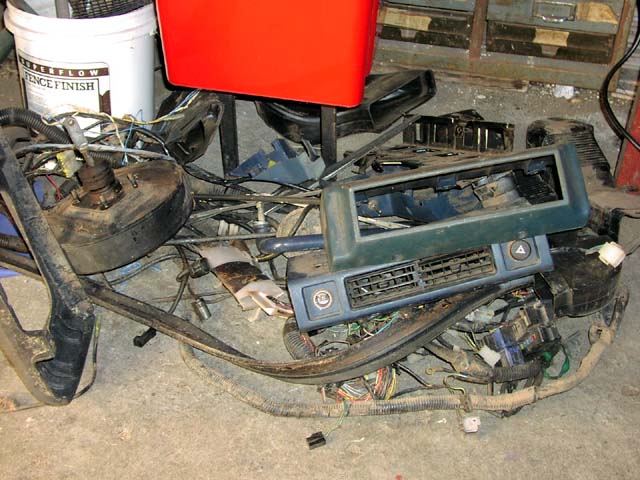
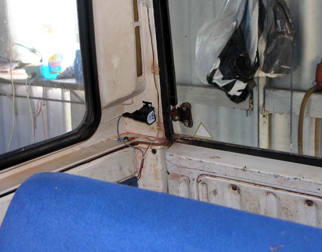
The entire dash was gutted from the donor vehicle including the wiring harness. Little did I realize at the time just how important it would be to have the harness on hand!
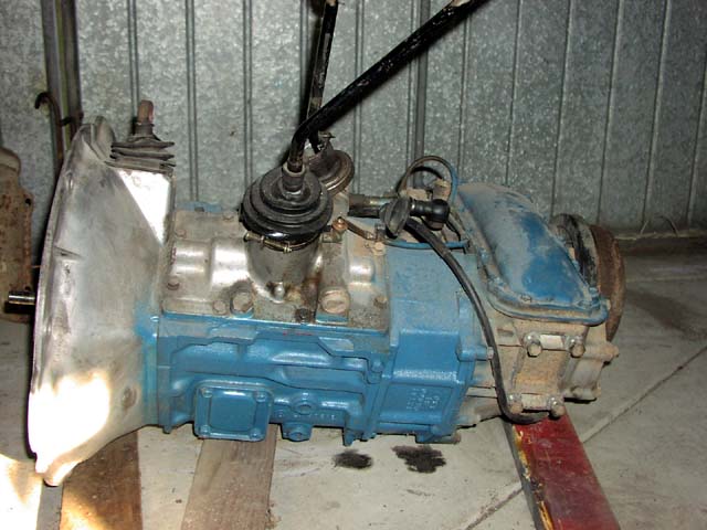
5 speed box & transfer case. This will be installed into my MQ at a later date. For now I'll have to keep living with the original 4 speed box.
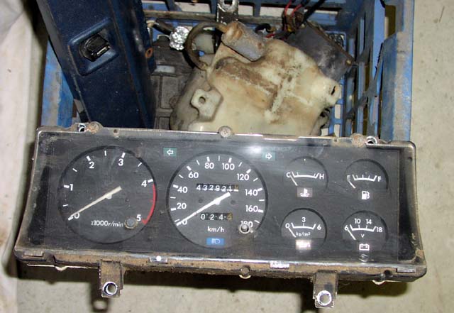
More bits, including the instrument panel and a tacho!
So, that sets the groundwork for the retrofit. I kept a diary of the installation, it took 10 days from start to finish and most were FULL days.
Tuesday (Arrived from the US in the afternoon):
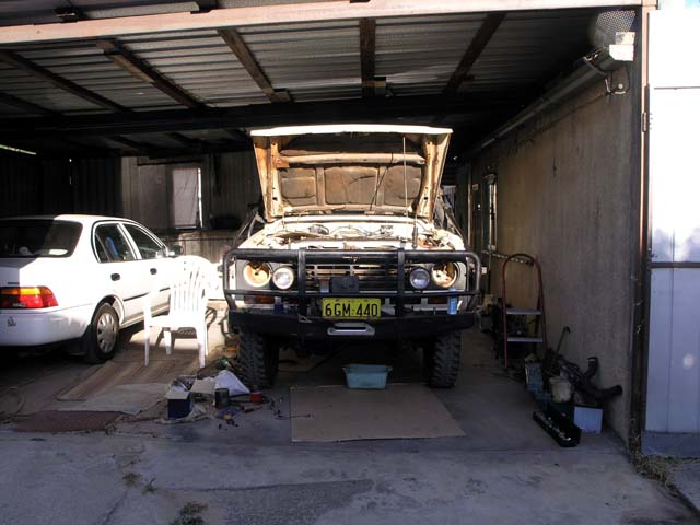
Start MQ and put into garage facing the lane.
Remove batteries.
Remove cover over DPC & Glow Timer & Glow Relay.
Organize donor parts & wiring loom and locate relays, control units etc.
Wednesday:
Remove Starter, Alternator, Injection pump 12V motor & Glow plugs from donor engine.
Test 12V Glow plugs, all functional.
Remove 24V starter and install 12V starter in MQ.
Remove & Fit 12V Winch Motor in MQ.
Remove fairlead and install hawse in MQ.
Remove winch solenoid module & remove all solenoids in preparation for 12V solenoid install.
Replace all rear brake/tail, turn, reverse light bulbs with 12V bulbs.
Replace number plate light with 12V bulb.
Remove trailer power converter (scrap) and solder wires directly (all now 12V).
Install large sunvisor on driver's side.
Remove entire alarm system (home made) and scrap.
Remove airfilter assembly and main battery holder (for access).
A long day but a lot accomplished. Here's some photos taken during the day.
Here's the starter out of my MQ. Bit of challenge to take out due to the after market turbo exhaust manifold but it does 'sneak' out.
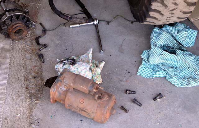
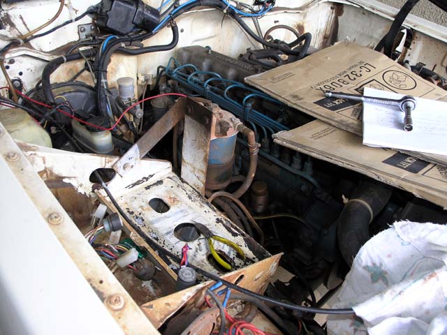
Main battery pulled and airfilter removed to allow access to the starter motor. The old winch on/off switch, which will be replaced with a 3 way switch later in the 12V retrofit procedure.
In the original 24V setup the DS had one battery that connected to ground and the +ve went to the Accessory relay via a fusible link (to provide 12V to the 12V accessories, like the radio, cig lighter AND 'bias' for the fuel and oil gauges). Then there was a power cable running from the +ve of the DS battery to the -ve of the second battery on the PS. That means that the -ve of the second battery was actually at 12V potential. The +ve of the second battery (at 24V potential) then connected to the starter motor. Fusible links from the +ve of the second battery connected to the main harness to provide 24V to everything from headlights, turn lights, horn, blower motor, wiper etc etc.
So, given the topology of the battery hookup I figured it would make sense to keep the DS battery as the auxiliary and the PS as the main since it was the short run to the starter motor. Instead of wiring the 2 batteries in series, each would be set up as an independent 12V battery. The DS one would provide power to dome/cargo lights, cig lighter outlets and the uhf radio. A heavy +12V cable would then run along the firewall across to the PS and go to the battery isolator/marine switch. The PS battery would provide all vehicle running power and also provide 12V to the accessory relay. A heave +12V cable would also be run to the isolator/marine switch.
The isolator/marine switch is basically a solenoid system to combine (parallel) the batteries while the engine is running to charge them both. The marine switch allows the winch to be isolated from both batteries, connected to either one, or connected to both (batteries paralleled) and in the both mode it also allows for a 'self jumpstarting'.
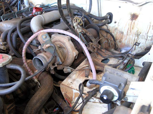
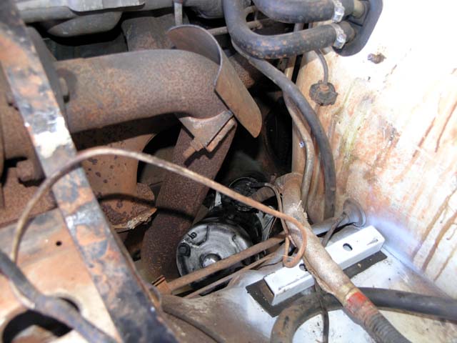
12V starter being finessed into place. I ended up having to unbolt (4 bolts) the exhaust manifold from the back of the turbo to allow the pipe to be moved an inch or so out of the way to let the starter line up properly with the flywheel to be bolted back up.
Next the winch retrofit from 24V to 12V. I purchased a new 4.5HP 12V Warn style motor in the US and brought it back with me.
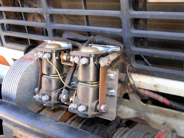
Here's the winch before I started the motor swap. NOTE: the solenoids on a 24V winch ARE 12V solenoids, each pair (cross connected) are wired in series - BUT read below! For 12V operation the control signals are rewired for parallel operation. Of course I bought 5 (4 + 1 spare) 12V solenoids thinking that Warn used 24V solenoids in their 24V winches. Guess I have 5 spare solenoids now :).
There is a subtle difference in the solenoids between a true 12V winch and a 24V winch. On a 12V winch ALL 4 solenoids have a common ground path through their body, hence only a SINGLE control wire goes to each solenoid and hence each cross connected pair is in parallel (12V operation). In a 24V winch the UPPER 2 solenoids have a common ground path through the body BUT the bottom 2 solenoids are DIFFERENT in that they do NOT have a ground path through the body. This means that the bottom 2 solenoids have 2 control wires and each one is wired IN SERIES with the cross connected mate - hence 24V operation. Took a bit of head scratching to figure out this subtle difference...
You can see how NEW the old solenoids look, the winch has been on my MQ for over 20 years - having a good fitting water proof cover is the reason. It may look all macho to have the winch exposed - but I'll keep the cover on mine...
Here's some new hookup info to rewire the 24V solenoid for 12V operation (remember that the solenoids ARE 12V, regardless of 24V or 12V operation - they are just wired in series for 24V and parallel for 12V).
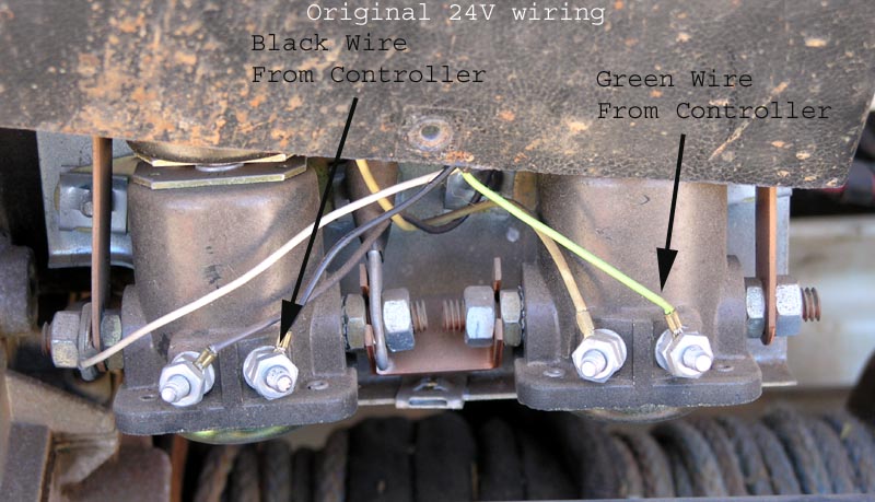
The following picture shows how the control box is wired for for 24V operation (as a reference). The key is to note where the Black and Green wires connect from the Control Box. Basically the Black and Green carry 24V from the hand control to energize one cross connected solenoid pair or the other cross connected solenoid pair.
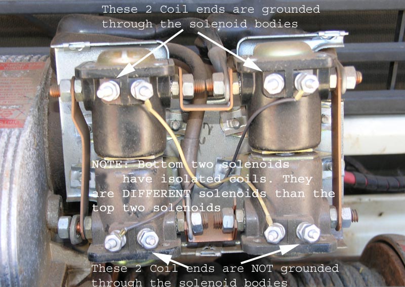
The next picture shows the original wiring (that will be left EXACTLY in place). The ONLY thing that needs to be 'rewired' is the Black and Green wires from the Control Box and the addition of 2 new wires to provide Ground connection to the bottom 2 solenoids. As noted in the picture the top 2 solenoids are DIFFERENT than the bottom 2 solenoids (i.e. they have DIFFERENT part numbers).
The next picture shows where the Black and Green Control Box wires need to be rewired to. It also shows where new Ground wires need to be connected to the bottom 2 solenoids. You can wire the new bottom 2 solenoid wires to the top two solenoid coils (where there are no wires originally - since those two 'lugs' are electrically grounded through the body of those 2 solenoids).
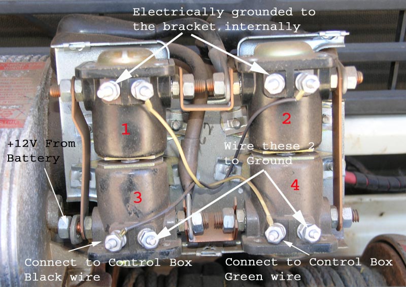
Once you have added in the new ground wires for the bottom two solenoids AND moved the Black and Green Control box wires to the new positions what you have done is wired the solenoids in Parallel (for 12V operation) rather than in Series (for 24V operation). So, for 12V operation Solenoid #2 and #3 coils are in parallel and Solenoid #1 and #4 coils are in parallel. (Originally, for 24V operation, Solenoid #2 and #3 coils are in series and Solenoid #1 and #4 coils are in series).
That's all there is to it. Of course you ALSO need to change the motor to a 12V unit as below...
The new 12V winch motor installed into the top of the gear box. Anyone need a good running 24V Winch motor? Once the back plate is removed off the motor the brushes will be exposed and they will slide off the commutator. that allows the motor to be pulled clear of the housing and installed onto the gear box.
Close up of the motor installed in the box. I chose the original style keyway motor from the supplier I bought the motor from. I had to clean off the old sealant and then applied some new non-hardening gasket forming material. Pretty simple looking in there eh? The knob on the left just slides the gear on the motor shaft clear of the large gear - that disengages the motor and allows the cable to be easily pulled off the drum.
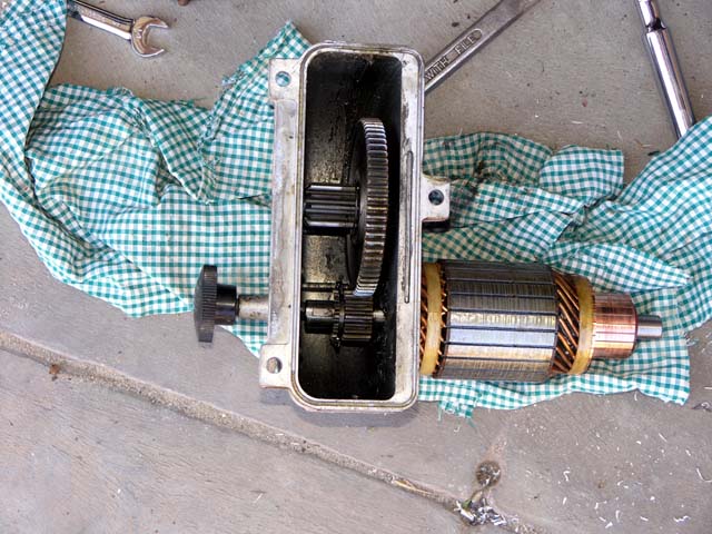
The 'bottom' part of the winch. Just another bunch of gears. Not much to a winch, basically an electric motor and a whole lot of gear reduction. The 8274 is oil lubricated and there's a 'bit' of oil at the bottom of the housing that the gears splash up when running.
Thursday:
Install 12V glow plugs.
Modify & test Glow Timer module for 12V operation.
Put plugs on 12V Glow relay.
Install 12V washer bottle.
Install 12V intermittent wiper amplifier module.
Install 12V front marker, turn and parking lights bulbs.
Wire winch solenoid module for 12V operation (using old solenoids!) and test winch, ok.
Install Starter 12V relay.
Install 12V Hazard light flasher.
Install 12V Turn flasher.
Remove old Winch engine bay power switch.
Clean & apply rust converter to aux battery tray and to DPC/Glow timer/Relay cover.
Install 12V 55W bulb in rear spotlight.
Another long day.
My original plan was to use the 12V glow timer module, but it turns out that in the 12V version, nissan changed the design (totally different case) and also moved the timer into the cabin. So, not wanting to do a major rewire job and wanting to keep my wiring harness intact, I tested the 24V glow timer and found it worked fine at 8V except for the internal relay. So, I retrofitted a 12V relay I had laying around and 'converted' my glow timer to 12V operation. This allowed me to just plug it back in and leave it in its original location.
WOW - look at that, and ACTUAL integrated circuit in a diesel vehicle :)
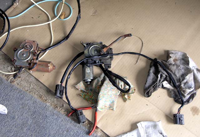
My 24V DPC motor on the left and the 12V on the right. Nissan went to rectangular style connectors so I had to cut the connector off my harness and replace it with the new style off the donor harness. I also had to remove the cable between the DPC and the DPC motor from the donor harness. Having the donor harness was a lifesaver! I also bench tested the 12V DPC motor, even though it came from a running engine.
The Glow timer, glow solenoid and DPC removed - you can see the connectors on the left side of the aux battery tray. Before working on the replacing the units with the 12V versions, I am going to clean, rust proof, paint and then coat the battery tray area with roofing 'goop'.
Friday:
Installed 12V blower fan with sticky foam and drilled out mounting holes.
Installed 12V Injection Pump Control Motor (removed wire bracket), tested good.
Installed DPC wiring harness (rectangular) to 12V Injection Pump Control motor.
Spliced in DPC rectangular connector for 12V DPC.
Installed Turn Flasher connector and mounted Turn flasher.
Painted DPC/Glow Timer/Solenoid mounting plate.
Painted and coated Aux battery 'tray'.
Installed 12V 100W bulbs in front spotlights and ran wiring to passenger fender.
Installed front number plate.
Connected Winch ground to engine.
Installed 12V horn, tested good.
Tested 12V small bulbs for Dash, all good.
Another day of finding things that nissan changed. Even the blower fan couldn't just 'drop in'. The mounting holes were made smaller, so I had to drill them out.
I also had to splice in the signal flasher from the donor harness since the 24V flasher was not a standard pinout. Again thankful of having taken the entire harness from the donor vehicle!
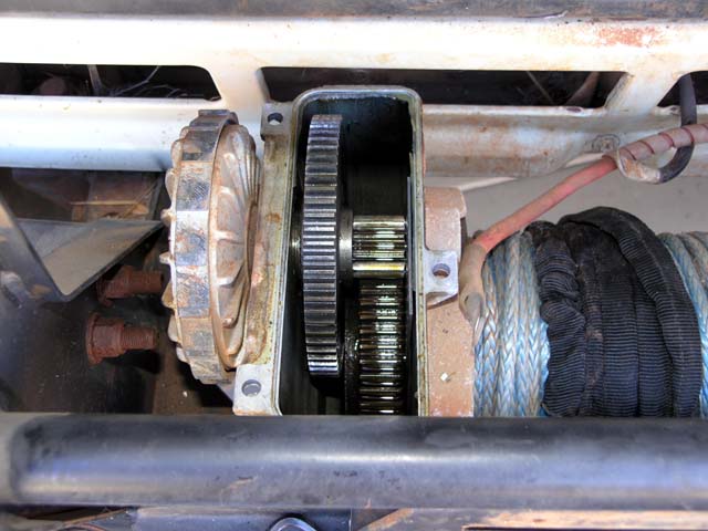
Not many pictures today - so here's one showing the winch all done and the aluminium hawse for the synthetic cable.
Saturday:
Installed Aux Relay.
Spliced in PS door pin switch (purple wire) to DS switch, harness at right of Driver's seat.
Installed passenger side sun visor.
Installed 12V bulbs in air vent and warning panel under instrument cluster.
Installed 12V horn relay, tested good.
Cleaned up +12V/GND wiring to cassette/radio. Ran dedicated light blue wire to aux battery fuse box in engine bay.
Loctite 'bump' stop screw for brake pedal, adjust brake switch.
Removed remaining alarm wiring, key switch and alarm 'light'.
Removed old car computer & wiring.
Installed DPC, Glow timer & solenoid and metal mounting plate, all done.
Removed 24V outlet on dash and dropping resistor and wiring.
Installed 12V cig lighter outlet in place of old 24V outlet (fused in main fuse panel with dedicated red wire running to aux battery.
Rewired ARB locker switches for 12V illumination. Green wire is ground and goes to compressor ground next to driver's seat.
Tested instrument cluster 12V bulbs, all good.
A bunch more wiring cleanup done today. Time to remove the instrument cluster and gain access to the old wiring that needs removing.
And once the instrument cluster was out I FINALLY found the horn relay - hiding... You can see it in the exact middle of the picture - hiding beneath where the instrument cluster normally sits. I guess nissan doesn't expect that relay to fail too often and I so far they're right.
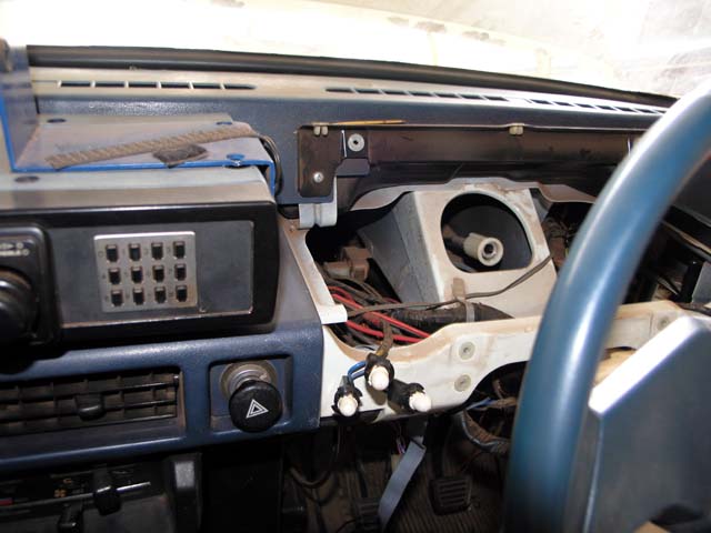
Now that's looking more like it. Lots of dangling wires under there and I start to cut and slash my old mods - a legacy of years of additions and changes. This was a great opportunity to clean it all out and start fresh with a new method to the madness. This time I documented the wiring colours and where the wires are going.
I also added a second 12V outlet under the factory outlet. Both outlets are wired to the Aux battery (via fuses) and always live.
Sunday:
Test, Hazard flasher & lamps, work.
Test, Turn Indicator lamps (front/rear & markers) & flasher, work.
Test, Brake lights and brake switch, works.
Test, Parking lights (front, rear and number plate & heater back light), work.
Test, Glow Timer & Solenoid & Glow warning Bulb, works.
Test, Horn and horn relay, Works.
Test, wiper, Intermittent, low & high speed. All works after repairing Intermittent amplifier.
Test, Passenger and driver's side switches for dome module, works.
Test, DPC and motor, cycles Start -> Stop correctly.
Test, handbrake warning light, works.
Purchased 4 battery terminal clamps (for main & aux batteries).
Purchased Relay for spot lights.
Purchased 12V semi-sealed headlights, 100W/55W.
Wired Keypad to connector, plugged into the computer and tested, ok.
I realized Saturday evening that nothing prevented me from at least testing the sections that I had already installed. First using a power supply to limit the damage if any wiring errors had been made, and then I hooked up the main battery with jumper cables via the fusible links.
Good success with all the lights and flasher units. In fact the only error was the wipers wouldn't return to the home position correctly and the intermittent feature didn't work. Looking at the wiring diagram it became apparent that the intermittent 'amplifier' as nissan calls it is also responsible for returning the wiper to the home position even if not being run in the intermittent mode. A quick disassembly of the amplifier showed a bit of moisture had gotten in there years ago and corroded a couple of resistors (one end no longer made connection to the PCB). The colour code was still readable and I had parts on hand and I did the repair. Still no luck, so I figured a capacitor near the corroded resistor leads may have also been damaged and so I replaced it too - success, the unit worked. So, some new gasket material to prevent future leaks and I reinstalled it into the vehicle and the wipers ran perfectly.
Tested the DPC and motor, though without having the engine start, only the Start & Stop positions are active in the cycle, but that proves that the controller and motor are sequencing correctly. Basically the way it works is that when the ignition key is set to the Start position, the DPC forces the DPC motor to go to the Start position which causes the injection pump to put more fuel into the engine. When the engine starts the alternator fires up and a signal from the regulator is used by the DPC to determine the engine is running and it then sets the DPC motor to the Run position. In the Run position the normal amount of fuel is pumped into the injectors. When the ignition is turn off (Accessory or Off) the DPC sets the DPC motor to the Stop position, this forces the injection pump to starve the engine of fuel and that's how the engine stops.
No photos for the day's work since it all basically involved testing, then I went to a mates place in the late afternoon for dinner. My so called day of "rest" :)
Monday:
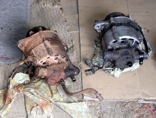
Removed 24V alternator from MQ. Transferred vacuum pump and pulley set to 12V alternator.
Removed A/C compressor and bracket and dropped bracket off to remove/weld tab in correct place for 12V alternator.
Ground off tabs on new 12V headlights, painted & installed MQ mounting hardware.
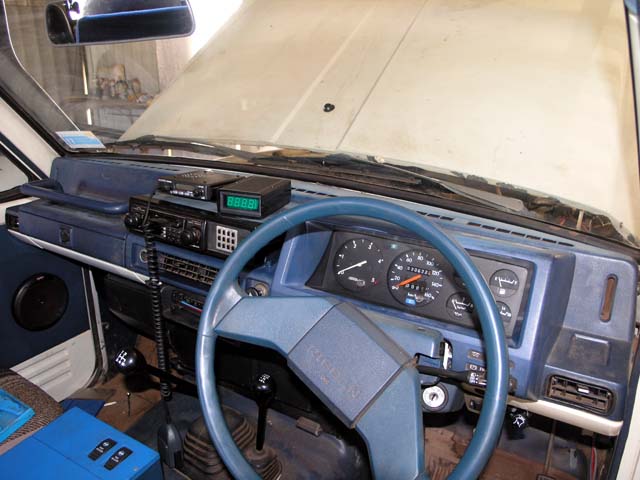
Installed 4 meter cluster into MQ instrument panel. Installed tacho.
Installed trip meter into MQ speedo unit.
Even though it appears that not much was done - a LOT was accomplished on this day. Removing the alternator required removing the A/C compressor (see below for the reason) and to get the alternator out required removing a bunch of stuff.
I'd put off removing the alternator for as long as possible, since I assumed it would be the largest job and I wasn't wrong. It took 5 hours from start to finish, including moving the bits off my alternator onto the donor 12V unit. It was also the job that drew the first blood on the whole project - skinned knuckle.
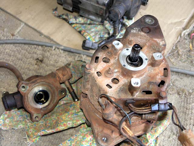
I removed the my vacuum pump (for the power brakes) and installed it on the donor alternator (on the right). I figured that since I knew mine was working fine I should use it. And then I made a nasty discovery - the rear mounting tab of the 12V alternator was NOT in the same position as the 24V unit. That meant cutting, moving and welding the tab on the bracket into the correct position. I also moved the pulley set off my alternator since the donor alternator had a bit of a ding on one of the pulleys.
By now the astute reader has probably noticed that it's easy to tell my parts from the donor parts. Mine are all coated/caked in dry red dust/mud from years of going into the outback. It's pretty clear that the donor vehicle lead a much more sheltered life away from the red dirt of inland Australia.
I figured since I knew my vacuum pump (for the brake booster) was working that I should transplant it to the 12V donor alternator. Here is a picture of it removed from my 24V alternator and you can see the splined shaft that exits the rear of the alternator.
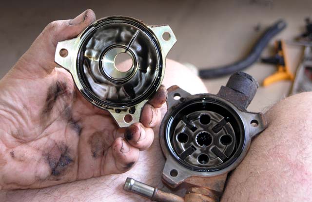
The guts that make up the vacuum pump. Looks like a rotary vane style pump. The pump is supplied with oil from the engine. The turbo also gets its oil fed from the same place.
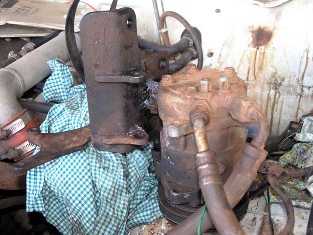
The bracket (and A/C compressor) removed from the engine. I had to drill out one of the bolts holding the A/C compressor to the bracket - you can see the metal shavings. It just didn't want to break free. Once drilled out it came out easily. I then dropped the bracket and alternator off to a local panel shop to get them to cut/reweld the tab - for $40 it saved me the trouble.
Tuesday:
Installed 12V relay above fuse panel, it is the brake test relay.
Installed Aux Fuse panel next to Aux battery.
Installed 10A fuse and wired connection to Diff Lock airvalves and switches. Tested, airvalves activate, lights illuminate.
Installed 10A fuse and and wired 12V relay for rear spotlight, tested, works.
Installed 15A fuse and wired to air compressor, tested, works.
Wired Radio permanent 12V via blue wire to pigtail wire going to tail/room fuse (for settings and clock power). Spare brown pigtail left with shrouded female spade connector.
Soldered lug on Aux battery -> Marine switch. Ran cable across the top of the firewall with the Accessory Relay wire & fusible link, ready to install to main battery.
Installed headlights, tested low & high beams, work.
Installed Hall Effect sensor into MQ speedo unit, tested, works. Soldered on cable &connector. Instrument cluster complete except for 'cutout cover' for tripmeter 'slot'.
Measured Tacho frequency response, 25Hz = 500RPM displayed (exactly).
Mostly an odd & ends wiring day. Installed the fuse panel to the aux battery. You can also see the large battery cable sitting waiting for the the aux battery. The battery cable is the +12V connection an goes along the firewall across to the passenger side where it will connect to the marine/solenoid setup.
The original 24V headlights (sealed units) have been removed in preparation for fitting the semi sealed 12V units. The sun is still rising, about 6am.
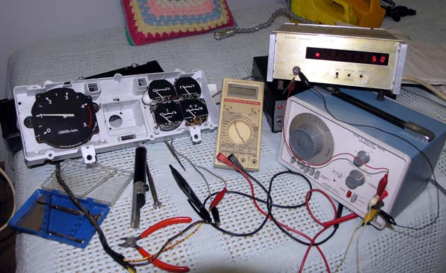
Testing the tacho with my VERY old home made frequency counter and and similarly old signal generator. The tacho is pretty well spot on 1000RPM per 50Hz. It takes an AC coupled signal >1V peak to peak before it detects an input. I need to build a controller for the tacho, haven't figure out the source of the input signal yet. The donor vehicle has an inductive pickup installed in the timing cover, but I don't plan to try and install all that stuff onto my MQ. I might just put an inductive pickup somewhere else and build a small uController based module that converts whatever that pulse rate is to the 1000RPM per 50Hz of the tacho. That will give me the factory tacho unit but with my own inductive pickup. This will be another year's project...
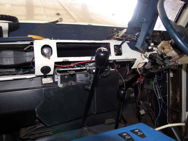
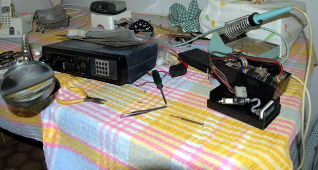
Radio pod, new and old trip computers and turbo timers. Various meters and bits. Several projects going on at the same time, getting the instrument cluster converted over to the new set AND getting the new trip/timer computer installed on the radio pod.
I ended up using my speedo, since the donor speedo had a different 'coupling' to the cable (nissan strikes again). I did transplant the tripmeter from the donor cluster to my speedo (all the mounting points were there). So I now have a donor tacho, donor meters, my speedo (with my odometer) and the donor trip meter with my instrument PCB (since it has the round style connector that mates with my harness). Life wasn't meant to be easy...
Wednesday:
Received UHF radio & Antenna, tested, works.
Instrument cluster all reassembled and installed. Tested backlights and they work.
Wired harness between the computer and the Speedo Hall sensor and also wired into the IGN SW circuitry and bypass switch.
Picked up alternator & A/C bracket and painted weld area.
Bought coolant to refill radiator.
Mounted computer on top of Radio.
Installed Wiper arms and blades.
Loaded new firmware into computer to allow entry of time during turbo count down. Built avrdude parallel port programmer.
Ordered a GME 3400 yesterday and true to their words it was delivered by courier today. Finally moving into the 21st century as far as vehicle communications go...
I found a missing feature in my trip/timer computer and so I had to build a brute force programming cable (since the programmer I brought with me didn't support the version of the uController I used - doh!). I had the source code and development environment on my laptop, so it wasn't too big a deal to change the source, compile and download/burn it into the uController. All works great now.
Last trip back (2 yrs ago), while using the wiper it stopped working. I could hear the motor running but the wipers wouldn't wipe. When I got back to Perth and disassemble the air vent grill I found that the area was chock a block full of years worth of debris - sticks and nuts and leaves etc etc. They had jammed the wiper control rods so badly that the ball joint had popped off and that's why the wipers wouldn't wipe. After cleaning out all the flora I replaced the motor back then with the 12V unit. I also put some 'mesh' under the vent slots to try and prevent it filling up again in the future. Since I couldn't power up the 12V unit in situ I had left the arms and blades off since I didn't know where the 'home' position was at the time.
Picture of instrument cluster reinstalled into the dash. The original speedo has an orange needle, the donor meters & tacho have white needles. I kind of like the look myself. Also, the new meters have a fancy translucent design to allow the back light to illuminate the gauge better than just from light coming through the sides - quite snazzy. Of course the speedo is the original - so it has to rely on the side illumination, oh well, it worked fine before.
You can also see a roll of tape on the seat in the foreground. It's the self vulcanizing kind that bonds and fuses to itself. GREAT stuff for covering wiring connections and battery cable ends if you want them to be reasonably weather tight and not come unraveled after a few years when the 'stick' goes away from normal insulation tape.
Thursday:
Installed DS air ducting and fascia with Bypass Switch.
Measured "OFF" battery current - 0mA (previous draw was due to dome being turned on).
Installed A/C compressor & Alternator.
Reinstalled belts, radiator hose, radiator cowling, throttle body.
Installed "White" (White/Green stripe) wire from Alternator Regulator via fusible link to main battery.
Installed Alternator regulator.
Made Ground cable for main battery.
The big job today was to reinstall the A/C compressor onto the bracket and the alternator. It took a lot less time to put it back together versus removing it. Lots learnt from the disassembly process :)
The A/C compressor is on the bracket and it's bolted back up to the engine. Next step is getting the alternator installed.
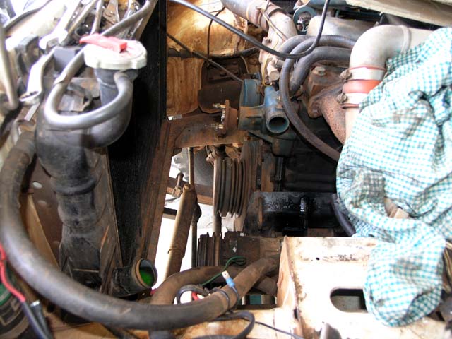
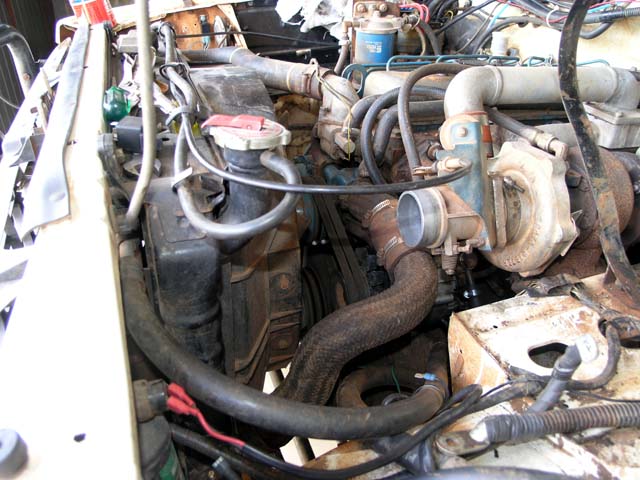
The alternator is back in, along with a lot of the other bits! There's a couple of hours work from the picture above to the picture below. On a diesel, the alternator is more complicated by having the vacuum pump on the back. That means having to hook up 3 hoses (oil feed & return and vacuum line) in a small constricted space (due to the turbo) and exhaust...
The 12V regulator uses one extra wire (a direct connection via a fusible link to the +ve of the battery). The rest of the 5 pins are the same as my 24V setup and it uses the same connector (6 pin). So, I took the 'missing' pin and a length of cable from the donor harness and 'clicked' it into my connector and spliced it to one of the fusible links. I presume the feed is to provide more accurate voltage sensing directly from the battery, presumably more critical in a 12V system than 24V.
Friday:
Installed main battery ground cable and main battery.
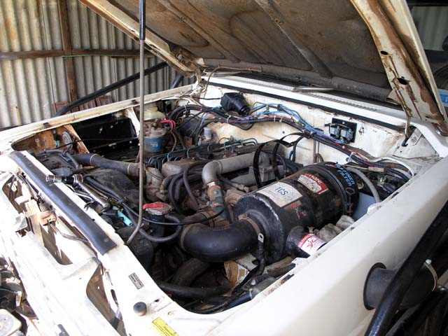
Installed Air filter assembly.
Started - RUNS!
Measured battery while running (~13.5V)
Made Aux battery ground cable and installed.
Installed Aux Battery.
Wired 'Blue' wire from ARB backlights to DS parking light. Tested, works.
Wired Cig lighter Red cable directly to aux battery.
Tested Air Compressor, turns off when up to pressure. Tested air valves, both work.
Rewired Dome and Cargo LEDs to aux battery.
Ran separate Red wire to cargo area to Cig Lighter outlet.
Rewired Blower fan (reverse + & -) now blows correctly.
Replaced Blower fan resistor module (from donor), low/med/high now much more proportional.
Fill washer bottle, clean and adjust sprayer nozzles.
Looking good, the main battery in installed, the airfilter hasn't been screwed down yet, but it was close enough that I fired up the engine to test it out. Considering I had already tested the glow timer & DPC controller and injection pump motor, the only unknown here was whether the start motor would crank over and it did. I tested the alternator output by measuring the battery voltage while running at it was around 13.5V and a medium idle - good enough for a preliminary test.
After the major accomplishment of firing up the engine, the rest of the day was used cleaning up some loose ends. The blower motor was one issue, it appears nissan changed the wiring polarity when they switched from the 24V system to the 12V system. I'd noted when testing things out prior to the engine start that the blower didn't seem to be moving much air even though it was spinning at full speed. I guessed it was sucking (therefore wired backwards), and on checking, it was. A quick switch of the wires in the connector had the blower running the right way. I also switched in the resistor module (that provides the low/medium speeds) from the donor vehicle since it has a lower resistance than the module in my 24V MQ. I now have perfect low/medium and high speeds.
I also spent some time rewiring the front cig lighters and the dome & cargo lights to feed from the Aux battery when camping. I also ran a power feed to the rear with a cig outlet, as seen in the following picture.
Saturday:
Installed Radio pod. All works.
Removed instrument cluster and repair bad connection, oil pressure gauge now works.
Installed UHF radio and antenna. Ran UHF power under dash to aux fuse panel. Wired to same fuse as Diff Lock air valves.
Welded broken bracket on front bash plate.
An easy day. Installed the radio pod & trip/timer computer and the UHF radio/antenna. Drove the MQ around the block and all seems well.
All that's left is to1) wire the marine switch/solenoid charging system and winch power 2) install the relay for the spotties.
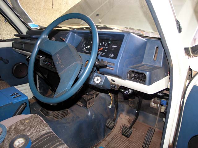
Here's the finished interior, dash all done and UHF radio working. Yes! Oh, yeah, still need to install the 'hook' for the UHF mike :)
Well, that's the end of the conversion. Having now converted my 24V MQ to 12V operation I only require a single 12V battery to start and run the vehicle. So, of course it was time to make the 2nd 12V battery into an auxiliary battery.
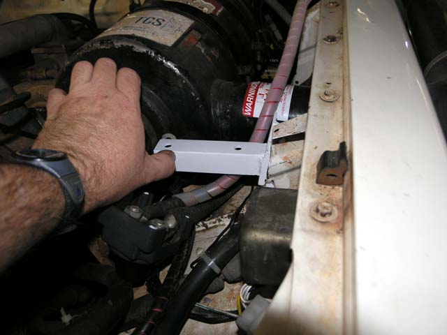
The first step was to fabricate a bracket to hold the marine switch, charging/isolating solenoid and control relays. I originally had a single position marine switch to isolate the winch from power, so I figured I could reuse the same location, just needed a new bracket.
The following picture shows a test fit of the finished bracket (painted even!).
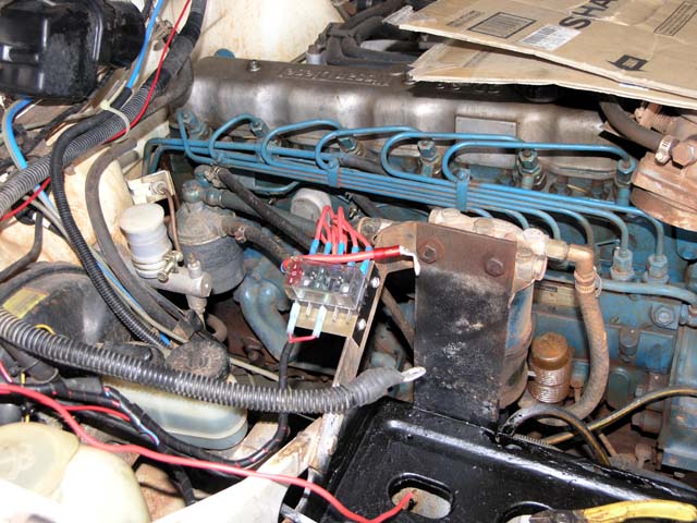
Here's the finished installation. On top is the marine switch that can direct either the main or auxiliary 12V to the winch, or both in parallel. The "both" position also allows self-jumpstarting. Under the switch (1/4" acrylic base) is a continuous duty heavy duty solenoid that is activated ONLY when the marine switch is in the OFF position and only when the alternator is up and running (i.e. engine is running and charge current is available).
Mounted under the acrylic base are 2 control relays that are used to engage/disengage the solenoid.
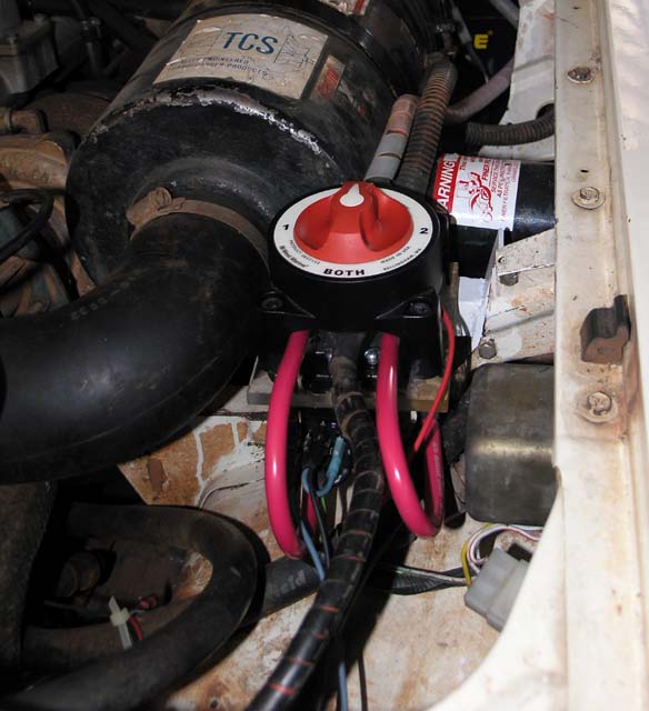
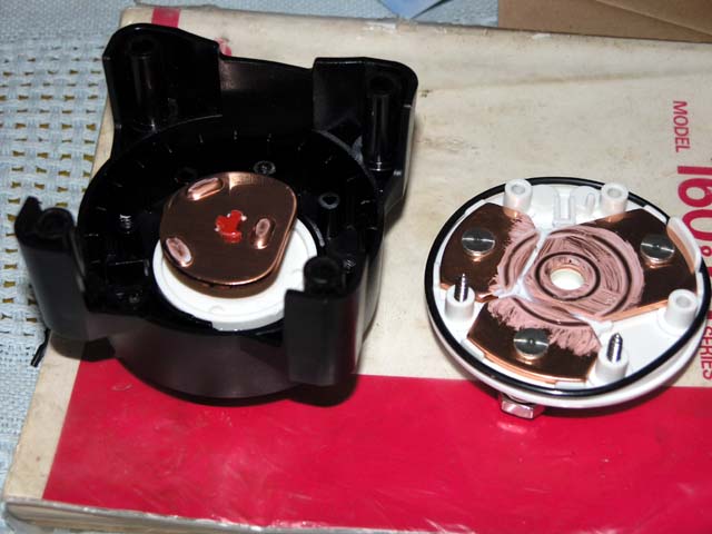
Just because I'm the curious type I pulled the marine switch to bits to see what the guts look like. Very heavy duty copper sections that carry the current (rated to 400+ amps). O-rings in all the right places too - very water/mud proof - good stuff!!
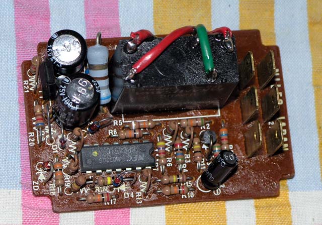
To create a control signal that would indicate that the alternator was running I had to design a small circuit. The MQ alternator has a signal L that goes to ground when the alternator is not running and goes high when it is. You can see the circuit and the relay/solenoid connections here.
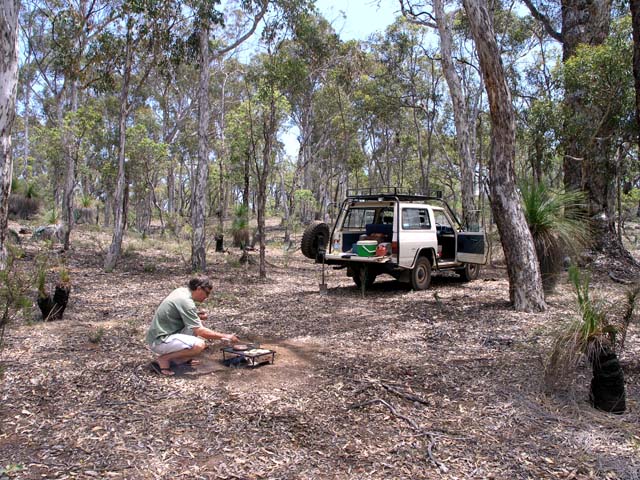
And that's it, all done and time for a BBQ with a mate - with the nissan running on 12V at an old haunt just out of Perth - Julimar State Forest.
![]()