Supercharger Install
Finally convinced myself to install a supercharger.
The first step was to remove my Thomas air compressor.
The second step was to install an EGT gauge.
EGT = Exhaust Gas Temperature
I was recommended to install an EGT gauge prior to installing the s/charger. By doing this I would be able to get a baseline set of readings for my engine that I could later use as a basis for determining when I should let up on the accelerator under heavy loads. Thanks to the pushing of Phil Postmus I did this - fortunately I found a place that had the EGT stuff in stock AND my s/charger was still in the 'mail' so there was no excuse not to.
I purchased an Auto Meter 3344 (http://www.autometer.com/), which includes a 2 1/16" OD gauge and a thermocouple probe and assembly kit. There are various ways of installing the probe, weld on, screw in and stainless steel clamp-on. I went for the hose clamp method, since it was the easiest to do and would be the easiest to remove if I later wanted to. The 3344 cost me US$120 including 2nd day UPS - reasonable.
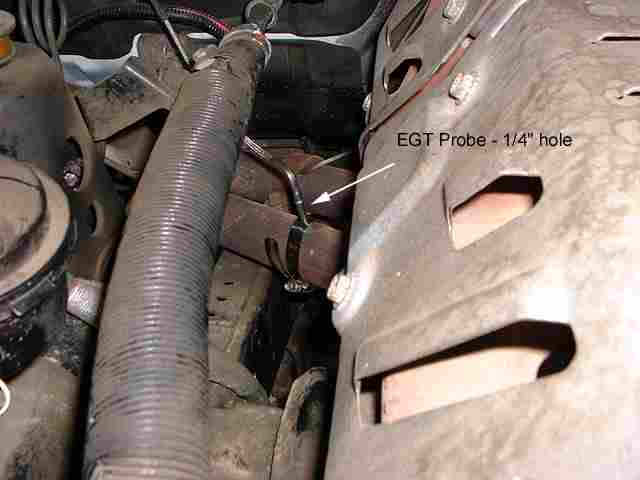
To mount the probe I drilled a 1/4" diameter hole into the exhaust pipe about 6" after the exhaust pipe/manifold junction (as recommended in the instructions). The probe has a collar that allows the tip to be place in the center of the exhaust stream. Once the collar is tightened, the probe can be inserted into the drilled hole and the hose clamp tightened.
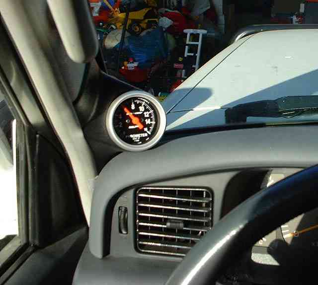
The next step after routing the thermocouple cable into the cabin was locating a suitable location to install the gauge. I originally made my own 'pod' and later bought a 'real one'. Below you can see the gauge installed into an Auto Meter pod made for the 80 - part number 15413. I bought it from http://www.egauges.com/
Next it was time to relocate the washer bottle - out of the vehicle. I already had a dual battery installation and initially relocated the washer bottle behind the cruise control module. The factory washer bottle is too big to fit anymore, because the outlet of the air filter assembly will interfere with it. Check out this link to see the new washer bottle & where it was relocated to.
And following is the 'exciting part' - the actual supercharger installation...
http://www.magnusonproducts.com/ has some interesting supercharger reading - they developed the supercharger unit for TRD.
I have the the manual (PDF) hosted locally here: S/C Install manual click here.
Thanks to Christo for some valuable hints and clarifications!
Firstly I'll document the TRD steps (from their manual) that I put installation notes/hints next to.
Step 6. Loosen distributor to remove No.2 water bypass hardline non-destructively. Remove only engine side bolts that retain the air cleaner housing. Loosen the hose clamp to the inlet side (or snorkel) and push the air cleaner housing 1/2" or so away from the engine.
Step 10. Bolts may be too long (most likely!) - dry fit first and grind shorter by a thread or two if necessary.
Step 13. Just slip a screwdriver under the VIN tag and rip it off.
Step 23. Installation of the hose to the thermostat housing and securing with the Adel clamps is performed easier if done just after Step 15.
Step 17. Loosen the front heat shield (three short bolts) this allows a spanner/wrench to get easy access to the nut on the stud (Flange nut C - in the picture).
Step 20. Make sure the hose clamps on the bypass hose DO NOT interfere with the operation of the bypass valve assembly. In my case I had to rotate the hose clamps relative to the picture to have the tightening bolts facing to the rear of the vehicle. The bypass valve's function is to equalized the pressure in the s/charger at cruise or idle when the s/charger is not required - this reduces the power loss dramatically. The valve closes under boost/acceleration conditions allowing the s/charger to pressurize the air to the inlet manifold.
Step 22. Rotate the throttle body before installing so that the three control cables run 'smoothly', i.e. try to have nice gentle curves in the control cables.
Step 25. In my case it worked better if I installed the relocated cable clamp upside down.
Step 33. The E, R and P black boxes on the picture refer to the letters stamped on the throttle body and EGR companion valve assembly where the two hoses connect to.
Tools you'll need:
The typical set of socket/spanners/etc of a reasonable DIY.
Crank pulley SST - or build your own (see below).
300ft.lb torque wrench for crank pulley bolt.
Long breaking bar - to break the crank pulley bolt loose and help fasten the replacement bolt back in.
Serpentine belt tool (15mm head) for tensioner - or build your own (see below).
Loctite 242 - thread locker - for some of the bolts/studs.
Loctite 518 - gasket former - for several of the s/charger assemblies.
Loctite 565 - thread sealer (only used in one place) - just use Loctite 242 unless you are REALLY picky.
Ok, lets get into it!
The first step (after reading the instructions!), is the removal of the fan. To remove the fan it is necessary to drain the radiator and remove the fan shroud and fan as a 'unit'. Removal of the battery & battery housing facilitates this process. The auxiliary battery and housing may be left intact.
During this phase the hardline (No. 2 water bypass pipe) for the coolant return from the throttle body needs to be removed. To non-destructively remove the hardline it is necessary to loosen the distributor adjusting bolt (mark it's original position) - on the '94 model we later did we didn't even have to loosen the distributor. The hardline can then be safely extracted.
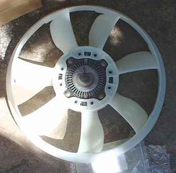
After removing the fan, the viscous coupling assembly is unbolted from the fan and reused on the TRD supplied replacement fan. The picture below shows the coupling installed in the new fan.
The TRD supplied ring fan has been found to be a poor 'mover of air' and not recommended at all. The fan from a V6 Toyota is a better choice or even a fan from the 3F. There's also now an option for a machined viscous coupling adapter and the ability to reuse the original fan. Searching IH8MUD in the 80 forum will provide you plenty of reading and options. Anyhow, the summary is to toss the ring fan in the bin...
The fun step in the whole installation is the removal of the crank pulley bolt - this is a 304 ft.lb bolt! Removal is relatively easy, use a big breaker bar with a 30mm socket. Unplug the high tension lead going fom the coil to the distributor - so the engine can't start. Next get your volunteer helper to brace the breaker bar against the chassis (the engine turns clockwise!) - then hop in the driver's seat and 'pulse' the starter for a moment - this broke my crank pulley bolt loose on the first attempt. Get a good breaker bar - on Amando's installation we broke the breaker ;-) Amando generously replaced it with a new Craftsman (lifetime warranty....) breaker.
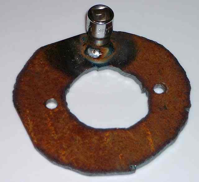
After removing the crank pulley bolt, you need to attach the TRD supplied supercharger drive pulley onto the crank pulley with the replacement bolt - 32mm head. The challenge is to torque the new bolt down - 304 ft.lbs remember! The trick is to lock the engine somehow because with the auto transmission the engine will turn quite freely. Toyota has an SST, I decided to save a big piece of change and make my own - have plasma cutter and welder, will fabricate ;-) The following picture shows the result - not pretty (in a rush and freehand cut) but functional. The hole in the middle is to allow the replacement bolt with it's washer to clear the tool. The two small holes allow the 'locating' bolts to bolt the tool 'through' the TRD pulley bolt holes to the original crank pulley (threaded holes). The welded 1/2" drive socket allows a breaker bar to lock the engine. A torque wrench with 32mm socket is then used to torque on the new crank pulley bolt. Once torqued up, the two locating bolts are removed, the tool is removed and the two locating bolts are re-installed.
New longer studs to accommodate a spacer are required (and supplied). To install them easily, remove the fan pulley temporarily (you don't have to loosen the belts!). To remove a stud, use two nuts locked against each other and then use a screwdriver to lock the water pump nose from turning - then remove the stud. Repeat for each stud. Install new longer studs and then slip the fan pulley back on and coerce the two belts back on - pretty easy.
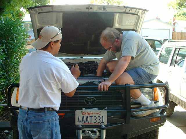
Spectator (Amando) and hard worker (Phil) preparing to reinstall the the new fan and shroud.
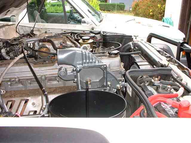
Now the fun really starts. As can be seen the air cleaner assembly is still in place - it does not need to be removed as stated in the TRD instructions - though if you can easily remove it (I can't since I have my aux battery switch etc) then you'll have extra room. If you don't remove the air cleaner assembly it will be necessary to remove the retaining bolts to the fender - just the ones nearest the engine (front & rear) - loosen the hose clamp to the air inlet ducting and slide the air filter assembly away from the engine by 1/2" or so. The MAF sensor and air line to the throttle body has been removed. Also, the supercharger plenum has been installed against the engine. Note that the main battery, shroud and fan have been reinstalled.
To install the plenum, the VIN tag must be removed (TRD step 13) - it is not necessary to remove the actual roundhead bolts as per the instructions - just push a flat head screwdriver under the VIN tag and 'rip' it off - it's soft metal.
To tighten the nut on the plenum mounting stud, loosen the bolts that retain the front exhaust manifold heat shield and slide the heat shield down a bit. This will give you sufficient room to fit a spanner/wrench onto the nut.
At this stage the idler pulley and tensioner can be bolted onto the front of the head. NOTE: it may be necessary (as in my case - and also Amando's) to grind the bolts down a thread or two - otherwise they may bottom out in the bolt holes.
The throttle body has been removed (along with the vacuum lines and coolant hoses) from the intake manifold. Move it to a secure spot and then ignore it for a bunch of steps.
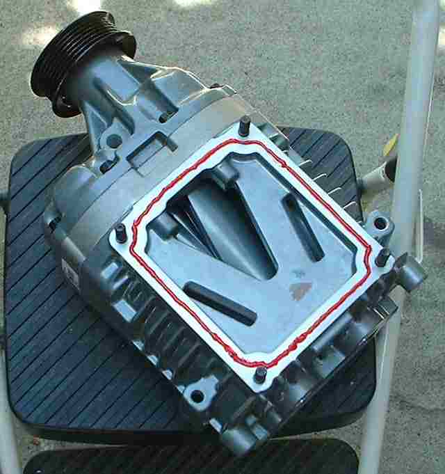
Time to bolt the supercharger to the plenum. Loctite 518 product is used as a gasket forming material. Ensure the mating surfaces are clean of grease and dirt. Next slip on the supercharger and bolt it to the plenum. I used Loctite accelerator product 7649 (in a spray can) to speed up curing. Clean all surfaces that the 518 product will be used on with acetone or a similar solvent.
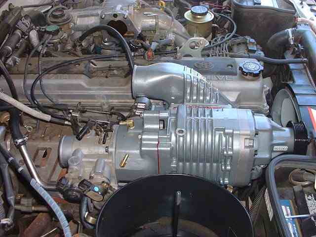
Starting to look better. The supercharger has now been bolted on. On the head (just behind the supercharger pulley) can be seen the tensioner and idler pulley. More fun to come later - putting the belt on.
The next step it bolt on the throttle body adapter. Note that the bypass hose between the plenum and the throttle body adapter is probably too long - I had to trim mine about 1/4". Also, make sure that the hose clamps are positioned such that they wont cause the bypass valve to stick. Placing the hose clamp as shown in the picture (i.e. the bolt end of the clamp facing away from the valve) will ensure you wont have problems.
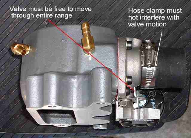
It also is a bear to get it to slip on AND get the 4 bolt holes to line up correctly with the supercharger. Keep at it and you will win ;-) The latest TRD superchargers (not for our cruisers) incorporate a 4th generation supercharger unit that has the bypass valve built in.
The next step is to bolt the throttle body onto the throttle body adapter. At this point the new extended coolant lines should have already been clamped onto the throttle body. This is starting to look real now.
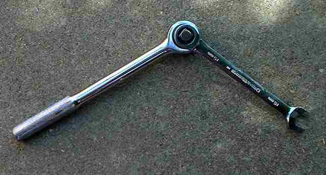
To slip the supercharger belt on requires the tensioner to be rotated to it's minimum tension position. There are serpentine belt tools to make this an easier job. I'm a cheapskate (yeah, I did buy the supercharger...) so I used a 15mm spanner (to engage the bolt on the tensioner) and a 1/2" drive ratchet into the ring end. This gave me a 'long' 15mm spanner that allowed me to rotate the tensioner without ripping out my knuckles in the process. The belt is a tight fit - but will slip over the supercharger pulley. Then gently release the tensioner. Once figuring out this technique it only took a minute or two to get the belt on. Another choice is buy a 15mm sacrificial socket and some u-channel steel (3/4" x 1/4" x 2') and weld it to the side of the socket (see below).
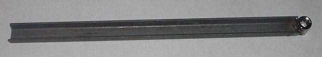
This is the tool I made for Amando's supercharger install. The bar stock is about 18" in length, welded to a 15mm socket. The socket end protrudes sufficiently beyond the bar stock to engage the bolt on the tensioner - worked great!.
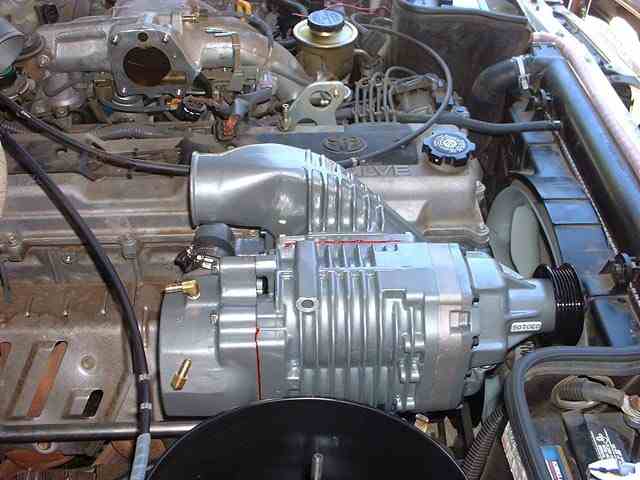
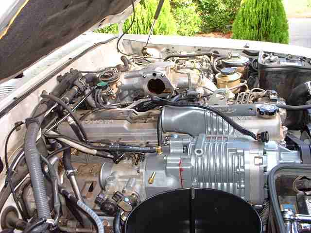
Hey - you can see that the supercharger belt is now installed - yeah! Also the brake booster line has been relocated and connected to the top nipple on the throttle body adapter. Note the extended TPS/IAC cables. The TRD instructions claim you can cut into the harness sufficiently to release enough cable to make the TPS/IAC connectors reach the relocated throttle body. In my case it didn't look possible. I cut the cables and extended them about 6", the solder connections were covered with 3M heatshrink with the internal heat sensitive adhesive - for a water proof seal.
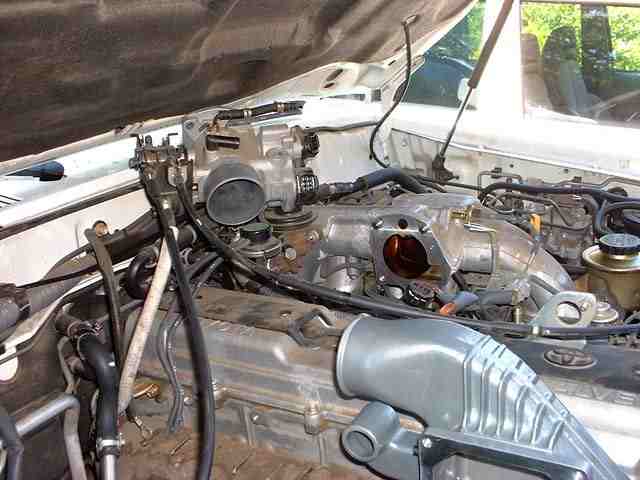
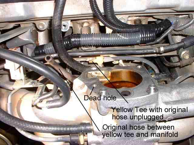
The following picture shows a critical step that is poorly documented (IMHO) in the TRD instructions. TRD says to connect a vacuum hose to an orange filter just under the intake manifold (not visible in the following picture). Actually what they mean is to connect the hose to the yellow tee. One nipple on the yellow tee is freed up by disconnecting the illustrated short hose that goes to the inlet manifold. That inlet becomes 'dead' because the hole (illustrated) will be covered by a gasket and then blocked off by the new intake runner. The yellow nipple has a short hose that goes under the intake manifold to the orange filter and a hose heading off to the right that is visible in the picture below. You can then unplug the short hose from the inlet manifold and optionally plug the nipple.
Also in this picture you can see the new slit loom covered TPS/IAC cables (running out from the main loom in the top of the picture). I slit part of the loom to try and extract enough cable length - but it was still too short. So, I extended the cables and then re-covered the loom. Nearly looks factory ;-)
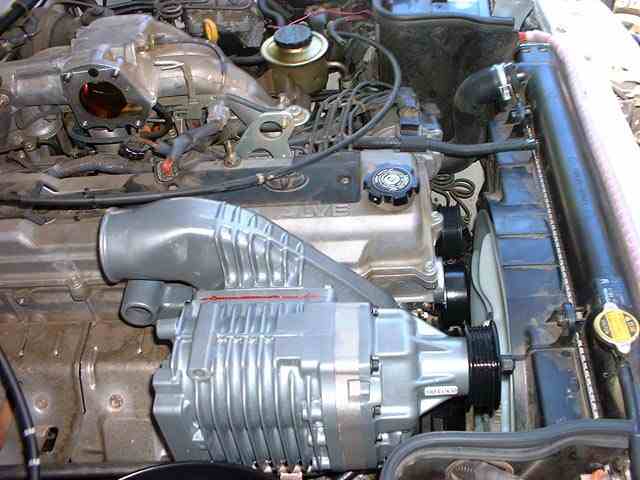
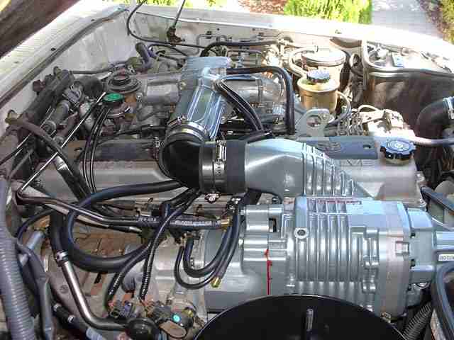
Nearly completed assembly. The intake runner has been connected to the plenum. Hey we're nearly ready to fire this puppy up. The hose clamps on the intake runner in the picture below have not yet been secured - that's why they are all 'over the place'.
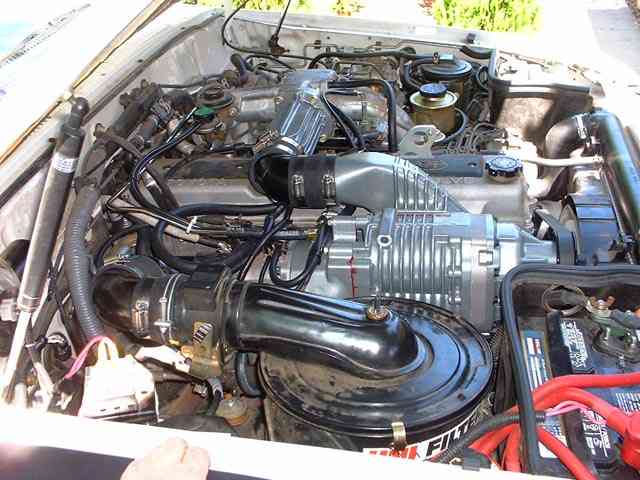
And here we are, it's all complete! Wow, about 10 hours total time into the project from start to finish. All that was left was to refill the radiator with red coolant and double check the connections prior to crossing fingers and firing up the engine ;-)
To get the hose over the MAF end of the air cleaner is another challenge. It has to be stretched because the OD of the MAF end is larger than the OD of the TRD elbow. Also, the supplied hose clamp would not fit over the OD. I managed to recycle one of the wire clamps from the original Toyota air cleaner to throttle body rubber pipe. Even that was a 'tight' fit. Also, I had to trim about 1/2" from this hose. The throttle body end hose was the right length.
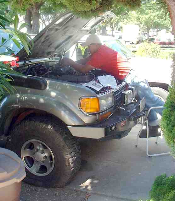
Not to be left behind, Amando had to get a s/charger too. With 35" tyres and spacers, it really helps to let most/all the air out! Of course his modified ARB makes it a bit easier to get to the engine.
Most of the hard work is done. The s/charger & plenum have been installed and the belt is on. The next time consuming step is to extend the TPS/IAC cables.
Yes, it does pay to read the instructions sometimes. You're suppose to connect the coolant lines to the throttle body BEFORE installing the throttle body onto the throttle body adapter! From start of the install to having the 80 on the road, 8 hours elapsed time - with a one hour lunch break - not bad!
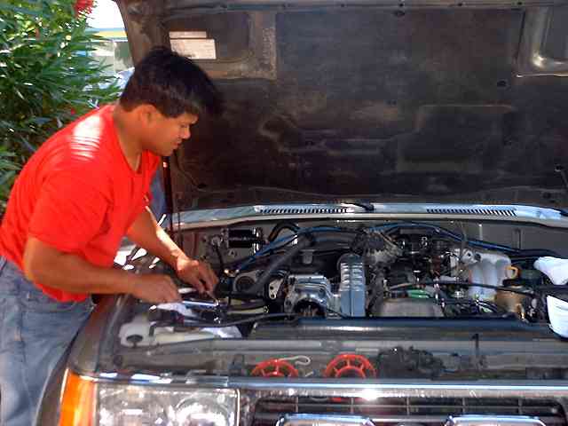
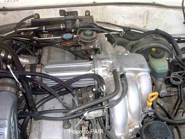
This section shows the additional steps to install a s/charger on a pre-95 cruiser. The pre-95 models have a PAIR valve that is smack in the way of the s/charger mounting location. To fit the s/charger the PAIR valve needs to be relocated. TRD has a kit for pre-95 models that includes a relocation bracket, new hard line connections to the exhaust manifold and a hose for one of the additional vacuum line connections.
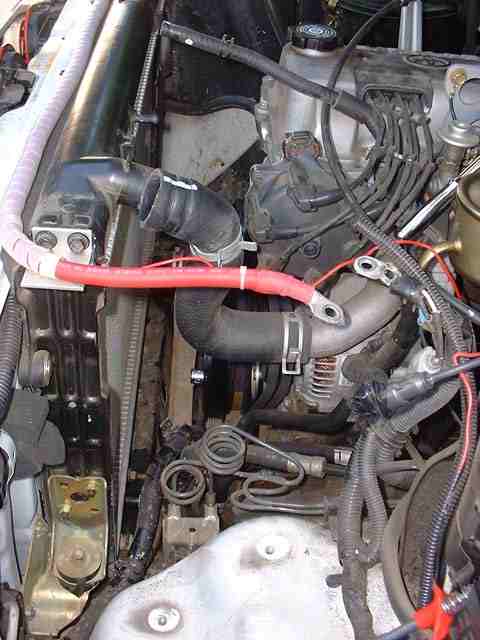
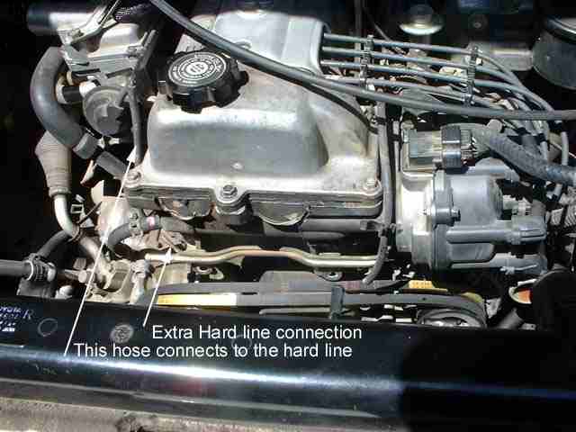
The following shows the additional hard line connection and the hose from the PAIR valve. This hard line needs to be removed since it is tack welded to the coolant hard line that also needs to be removed as in a post-95 s/charger install. The hose that is highlighted is discarded and replaced with a new (supplied) longer hose as shown at the end of this page.
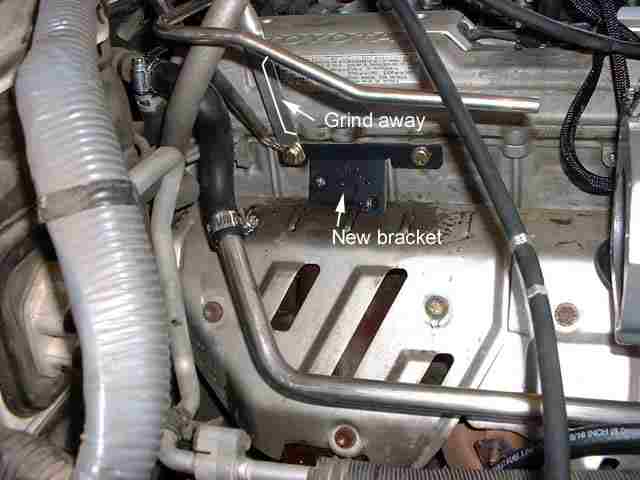
The following picture shows the PAIR valve relocation bracket bolted in place. Also highlighted is the part of the bracket from the TRD s/charger kit that needs to be ground away to 'clear' the PAIR valve assembly.
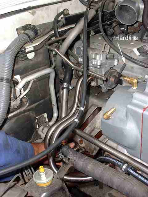
The following shows the PAIR valve bolted in place along with the new pipes that connect to the exhaust manifold. The 'Hardline' text is pointing to the original hard line that has been disconnected to install the PAIR valve. After it has been installed the original hard line can be plugged back in. It is a short hard line that runs behind the PAIR valve from one side to the other. It also has the connection that the new long hose terminates to (see next picture).
The following shows the extra vacuum line that exists on the pre-95 models. The pre-95 kit includes a hose to connect this to the original connection point on the PAIR valve.
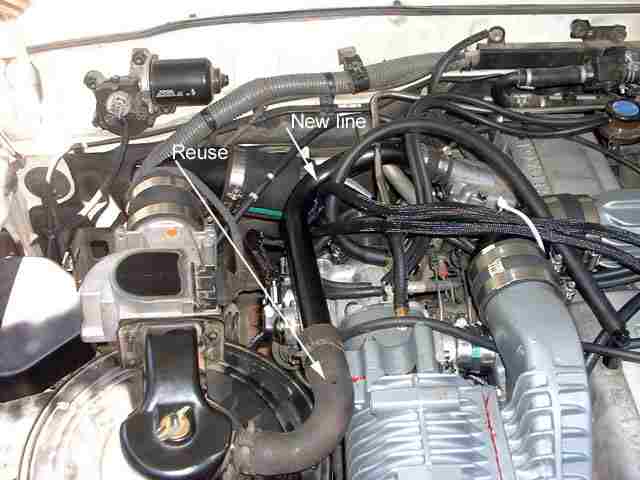
The finished s/charger installation. Highlighted is the new hard line that connects the PAIR valve to the air filter assembly. Note, you have to reuse (cut) sections of your original hose to connect from the air filter to the new line and also from the new line to the PAIR valve. The instructions included in the pre-95 kit document the measurements and where to cut the hose.
One BONUS of the s/charger installation is that you remove and discard the 'boom-box' on the air filter assembly so installing an auxiliary battery is real easy!
Current score - 5 superchargers successfully installed.
![]()