Auxbat 2025 update. I have moved to a LiFePO4 battery and DC:DC charger
Installing an Auxiliary battery in
an 80 series Land Cruiser is a relatively straight forward
procedure.
All mounting holes for a factory battery tray are already in
place on the US/PS fender.
One requirement is to relocate the factory washer bottle to make room for the factory battery tray.
Or if you have a supercharger, then you need a smaller bottle and you still need to relocate that. You can see a relocated generic washer bottle washer_scharger.
Following are the Toyota part numbers for the battery tray assembly and associated paraphernalia and quantities of each that are required.
In my case, deciding to save a few bucks, I only bought the tray from Toyota. I already had plenty of spare metric bolts from removing the stock bumpers and replacing with ARB/Kaymar. I bought a generic J bolt set from an auto store, which included rubber washers and nuts. The only other issue is that the tray does not come with the rubber gaskets that protect the cables that run through side holes in the tray. I source some appropriate sized grommets and all came out nicely.
Installing the battery tray is straightforward, further down shows a picture of a typical installation.
In addition you need to get the cables, the battery and a charging/isolation system.
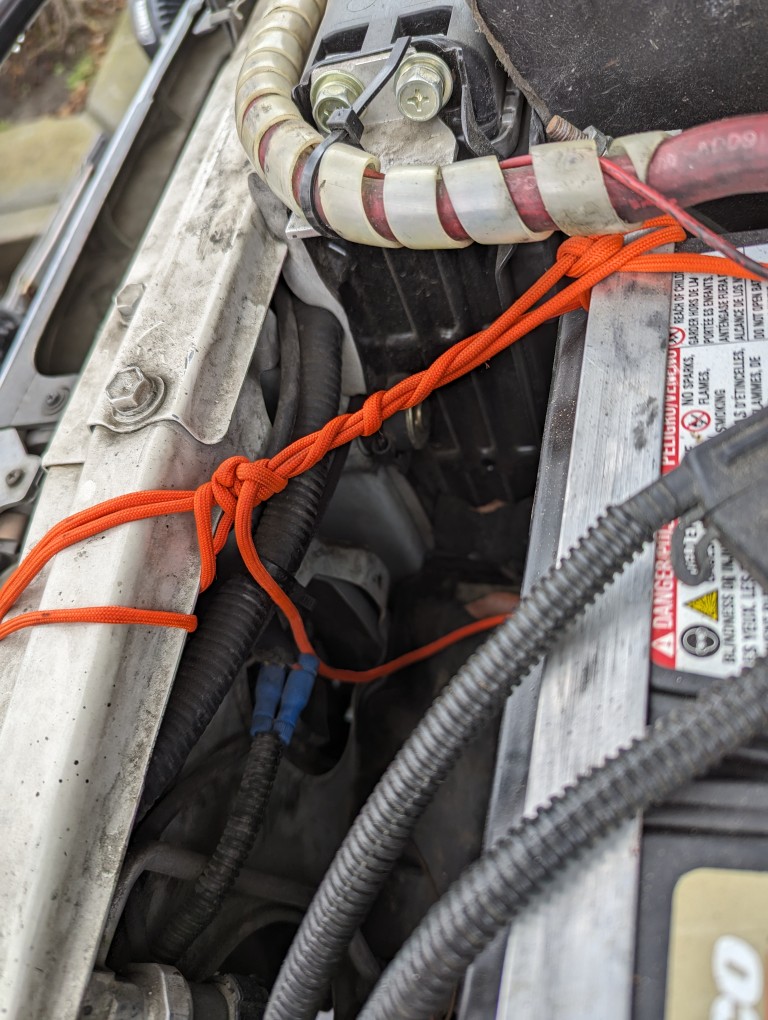
The original Toyota battery clamping setup has one side of the battery hold down grabbing the fibreglass battery tray. Over time (vibrations, offroad, corrugations etc), the hook creates a bigger and bigger slot in the fibreglass. On my Patrol, the battery hold down uses J hooks into the steel tray, much stronger. Since I was redoing the battery system, I decided to upgrade the hold downs on the 80.
What prompted fixing the problem once and for all was a 10 day trip through Death Valley. With a bunch of dirt roads and tracks continuously putting forces on the battery hold down, the J Hook in the fibreglass of the main battery started to seriously get damaged. Add in that the battery is held diagonally at a higher up point of the thin side even more flexing was occurring. On checking under the hood every day or so, I grabbed the battery and could rock it, even though the stock clamps were tight. To at least prevent the rocking motions continuing and damaging things, I used some paracord to at least dampen things a bit.
I had sourced new brackets and had
a plan (but not the time or incentive) to replace the silly stock
Toyota stuff. After this trip the incentive was now present. Then a few
months later the aux battery died of old age, so it was time to a)
rethink battery chemistry and b) fix and upgrade the battery cases and
wiring.
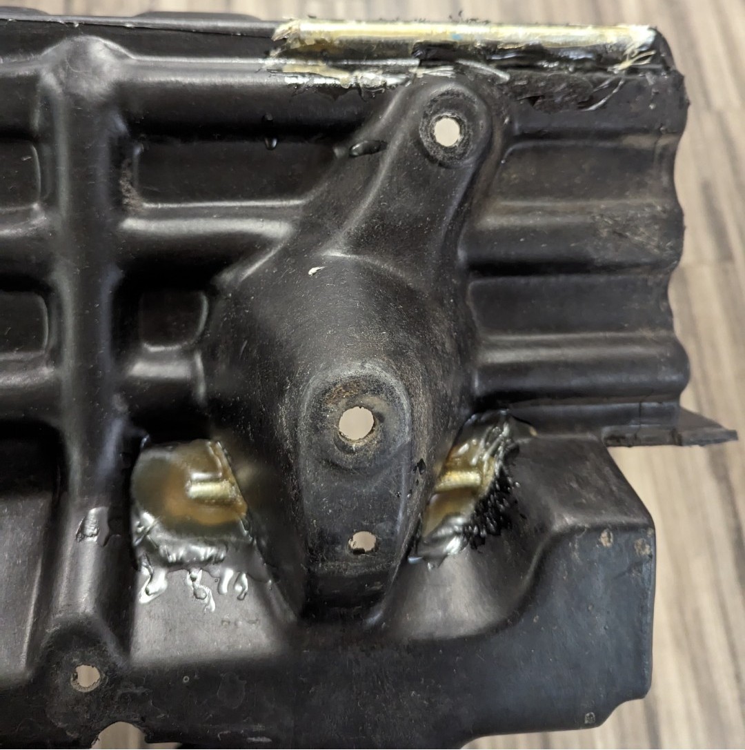
I sourced some steel rod and cut pieces to then epoxy (fibreglass mat and resin) to the battery tray for the new J hooks to grab. These would never rip out.
This is the bottom of the driver's
side tray. One pin epoxied along the edge and the other pin inserted
through the tray (holes drilled to allow the pin to slide in).
Same operation performed to the passenger side tray.
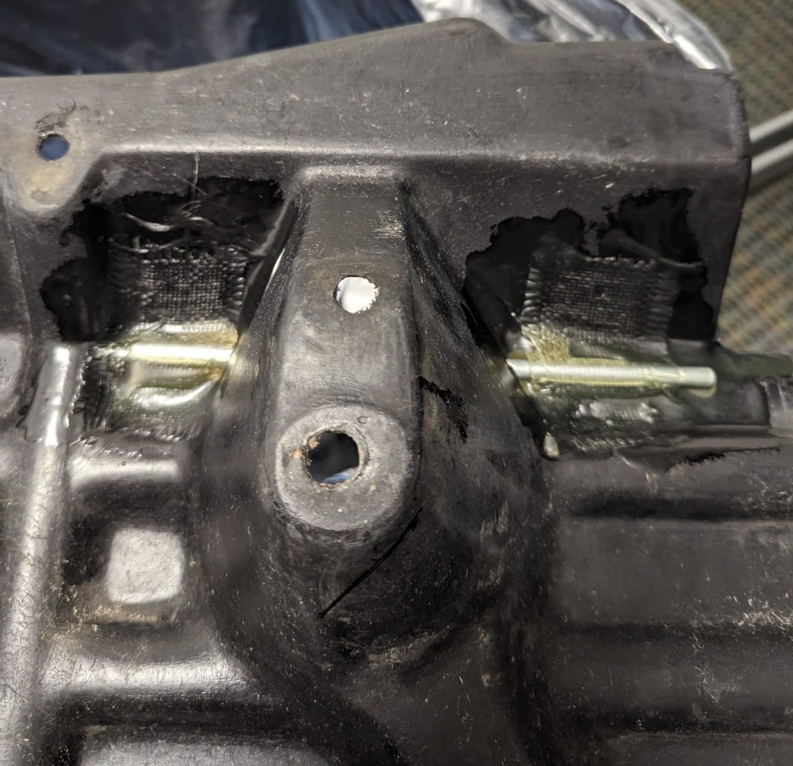
Jumping
ahead, the passenger side tray has been installed (after repairing a
lot of pre-existing damage, using more fibreglass mat and resin). You
can see one J hook that can be installed through the elongated hole,
then rotated to hook onto one of the pins. You can also see the front
pin and the other J hook will just grab it. I also repaired and closed
the original J hook hole and a second larger hole for a ground cable
that use to run to the block - not required with how I was going to set
up the LiFePO4.
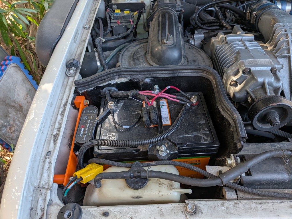
You can
of course see the installed Wagan 25A DC:DC charger that I chose to use
for charging a 100AH LiFePO4 battery. The orange bracket is a custom
design that I did using Solidworks and then 3D printed in PETG. The
bolts utilize existing captured nuts in the 80's body. There is also a
MIDI fuse holder for the charging output to the LiFePO4. Mounting holes
for the Wagan and Midi have 3D printed threads, M5-0.8 for the Wagan
bolts and M4-0.7 for the MIDI fuse holder bolts.
Downloadable STL file for the Wagan Charger bracket
Going to LiFePO4 chemistry for the auxiliary battery has pros and cons.
Pros:
- A 100AH battery can be drained to 'flat' and then recharged without damage.
- This can be done thousands of times, so you actually get the 100AH.
- An AGM/Wet Cell etc shouldn't be discharged below 50% and even that weill shorten the life of that battery.
- Self-discharge is very low, months can go by without damage
- They weigh a lot less, about 50%
- They are much smaller for the same capacity.
- Discharge voltage curve is much flatter, so most of the runtime will be above 13V, so you get more watt.hours.
- Battery life is easily 10yrs or more.
Cons:
- A good charger should be used to charge and maintain the battery. In this case I went with a Wagan multi-chemistry unit.
- Maximum discharge current for the 100AH battery is 100A, so it can't
be used as a starting battery. It could be used for a self jump start
in an emergency.
So, the real con is that you lose the ability to have a backup starting battery in case the main battery has a catastrophic failure (very rare, but I've had happen once - wet cell battery with shorted cell). Running an AGM as the main starting battery should provide reasonable reliabilit
The
repaired and patch aux tray. Over the years it had been damaged and
pieces had broken off on the left side. Using fibreglass cloth and the
epoxy resin and rebuilt the damaged sections and also closed off
previous grommet holes and created new ones that were better placed and
sized. Bit of black spray paint and it all looks good again.
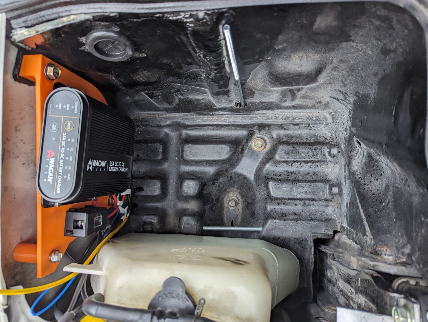
This is the final installed and wired setup. Wires are labeled for easy identification in the future. The Wagan charger supports various battery chemistries and will automatically charge when the main battery/alternator reaches a charging voltage state. It also support an MPPT solar input and will switch to it automatically as solar is available. The connection for an external panel is provided via the yellow SB50 in the bottom left of the picture below.
The new battery hold down clamp is also visible. Much more secure and robust than the original Toyota clamping setup.
All installed and final wiring and routing through the grommet is complete.

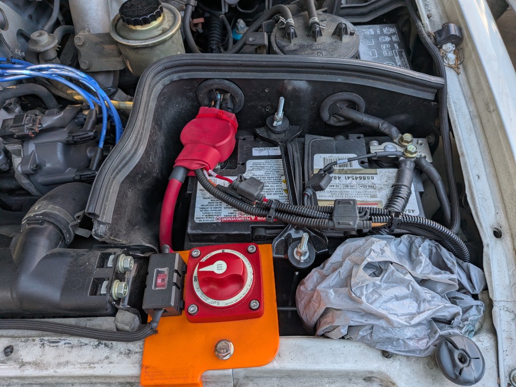
For the main battery I've been using and AGM for several years now and it has been performing well. I've also moved to different battery post clamps that allow multiple heavy cable connections to be made.
The original ground connections
to the block and to the fender have all be upgraded as per the original
dual battery writeup (still on this website). The heavy Red and Black
cables running forward are for the winch. The black goes directly to
the winch body.
The Red goes to the On/Off marine switch and the output then goes to
the winch positive.
This allows the winch to normally be isolated (protected from someone tampering with the winch control inputs) and to also provide a mechanism to turn it off if something in the winch controller or solenoids fails. The orange bracket is another custom designed unit and again 3D printed in PETG. The bolts that fix it to the body utilize original holes. The MIDI fuse protects the power feed going from the main battery to the Wagan DC:DC charger.
The marine switch is a Bluesea
6006 M-series unit. It is rated at 300A continuous and 500A for 5
minutes and 900A for 30 seconds. Certainly quite capable of dealing
with the M12000 winch. The rear mount/spacer of the switch is discarded since
it is not required for use with the bracket I designed. Holes for the
bolts in the bracket have threads cut into them as part of the 3D
printing process. MIDI uses M4-0.7 and the Bluesea M5-0.8 bolts.
Downloadable STL file for the winch switch bracket
The grey plastic bag just has a funnel for topping up oil during trips and a few rags.
AWG |
Nominal OD |
ohms/1000' |
Voltage drop |
8 |
5/16" |
0.62 |
0.06V @ 100A for 1' of cable |
6 |
11/32" |
0.40 |
0.04V @ 100A for 1' of cable |
4 |
13/32" |
0.24 |
0.024V @ 100A for 1' of cable |
2 |
15/32" |
0.157 |
0.63V @ 400A for 10' of cable |
1 |
17/32" |
0.127 |
0.51V @ 400A for 10' of cable |
1/0 |
9/16" |
0.099 |
0.40V @ 400A for 10' of cable |
The LiFePO4 battery I'm using has an internal BMS (as most do) that protects the battery from charging when too hot or too cold. It also has some overdischarge protection as well. The temperature rating makes it safe to operate in the engine bay, especially since the 80 has the nice battery cases that shield the battery from direct engine heat.
The Wagan DC:DC charger is fully sealed and waterproof and is also rated to be safe to operate in the engine bay.
![]()